
User manual


Service Menu Parameters
99
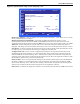
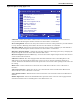
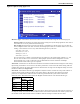
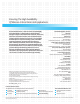
Figure 92 Options setup, page 5 of 5
Only characteristics for analog inputs used for custom sensors are visible in this menu.
Start Points, Lines S446, S448, S450 and S452)—Represent the starting point of each analog input’s
linear characteristic. The column on the left indicates the desired readout at the lowest allowable
sensor voltage, and the column on the right indicates the lowest sensor voltage.
End Points, Lines S447, S449, S451 and S453—Represent the finish point of each analog input’s
linear characteristic. The column on the left indicates the desired readout at the highest allowable
sensor voltage, and the column on the right indicates the highest sensor voltage.
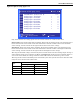
The range of allowable voltages is dictated by the Precision selection for that analog output on Page 4
of the Options Setup screen of the Service Menu (see Figure 91). If the precision of Analog Input 1 is
set to 0-5V on line S436, the voltage selection on line S447 will not be allowed to go above 5.0V.
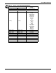
The range of the readout start/finish points is dictated by the units system selection on line S441. The
range for each is shown in the table below.
Measurement
Type
Units
English SI
Air Pres -1.25 to 1.25 inWC -320.00 to 320.00 Pa
Pressure -320.00 to 320.00 PSI -22.00 to 22.00 Bar
Temp -320.00 to 320.00 °F -160.00 to 160.00 °C
Percent -320.00 to 320.00% -320.00 to 320.00%
OPTIONS SETUP (page 5 of 5)
to change parameter
to confirm
to select parameter
for next/previous unit
then
UNIT 01
S445
S446
S447
S448
S449
S450
S451
S452
S453
S454
S455
PASSWORD (Actual Level 0) ????
Analog Input 1 Start Point = V
Analog Input 1 End Point = V
Analog Input 2 Start Point = V
Analog Input 2 End Point = V
Analog Input 3 Start Point = V
Analog Input 3 End Point = V
Analog Input 4 Start Point = V
Analog Input 4 End Point = V