
User manual


Operation
14
Chilled Water Units with Variable Fan Speed—EC or Variable Frequency Drives
Parameters related to VSD fan speed setting can be found in the Service Menu / Setpoints submenu
on page 5 of 6. This menu allows the cooling unit's fan motor speed to be configured and adjusted for a
variety of applications.
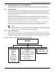
• Auto Operation: When set to Auto, the speed of the fan motor follows the position of the chilled
water valve based on predetermined logic for cooling and dehumidification operation. Auto
operation can be set with either return or supply air control. An exception is when the supply
sensor is set to Cooling Only. During this operation with the VSD Fanspeed set to Auto, the
chilled water valve is controlled by the supply sensor and the fanspeed is controlled by the return
sensor and its associated control mode settings.
• Manual Operation: When set to Manual, the speed of the fan motor follows user input as set
either locally at the Liebert iCOM display or remotely via Modbus communication, which works
in conjunction with an optional Liebert IntelliSlot
®
485 card.
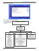
• Economy Operation (free-cool or dual-cool units only): When set to Economy, the speed of the
fan motor follows the Free Cooling or Dual Cool water valve. The fan speed output latches to
percentage value set at STD setpoint (Service Menu, Setpoints) when a compressor activates to
prevent the DX system from operating at low evaporating pressure, which might cause the coil to
freeze.
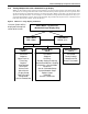
• Delta Operation: When set to Delta, the fan speed modulates in relation to two temperatures
that are read from a sensor board, which is optional. The sensor temperature readings will be
compared and a delta between the two sensors will be determined. The delta of the two sensors
will be compared to the fan speed delta setpoint and will determine the correct fan speed. This
control can be adjusted using the Fan Speed P-Band and the Fan Speed Integration to determine
the rate of change based on the sensor delta. Delta operation enhances air flow control when a
containment solution is being utilized. This is accomplished by maintaining the correct airflow
based on the inner and outer containment temperatures.
Additional fan speed configuration parameters include a fan speed filter and fan speed reposition
delay timer. These parameters allow fine tuning of the fan speed control and, except for setting to
Manual, are applicable to any other operation mode set in the VSD fan speed setting.
• The fan speed filter allows the fan to respond at a different rate depending on the location of the
control point within the proportional band.
Example: When the controlled temperature is near the setpoint or at conditions where the pro-
portional band output is decreasing and approaching 0%, the fan speed change rates are pro-
portionally decreased to avoid overshooting the controlled temperature. However, when the
temperature rises above the setpoint or at conditions where the proportional band output is
increasing, the fan speed change rates are proportionally increased.
• The fan speed reposition delay timer setting in the Liebert iCOM menu can be changed to
improve the fan operation stability if it is oscillating. The delay timer holds back the fan output
change until each delay period is reached if fan speed is decreasing. If fan speed is increasing,
then the delay timer has no effect.
NOTE
• The fan speed lower and upper limit settings are normally set at the factory.
• The standard fan speed control will be overridden during a call for Dehumidification. When
there is a call for Dehumidification, the fan speed will change to the VSD Setpoint Dehum
parameter found in the Service Menu, Setpoints.
• The standard fan speed control will be overridden during a call for Humidification or
Reheat. During a call for Humidification or Reheat, the fan speed will change to a higher
speed, which is set at the factory to eliminate the possibility of condensation or damage to the
unit.