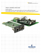
Monitoring For Business-Critical Continuity™ Liebert® IntelliSlot® Web Cards Installation Manual Liebert IntelliSlot Web Card, Liebert IntelliSlot Web Card-LB, Liebert IntelliSlot Web Card-LBDS, Liebert IntelliSlot Web Card NXL™, Liebert IntelliSlot Web Card-L, Liebert IntelliSlot Web/485 Card-ADPT
TABLE OF CONTENTS IMPORTANT SAFETY INSTRUCTIONS . . . . . . . . . . . . . . . . . . . . . . . . . . . . . . . . . . . . . . . . . . . . . . . .1 1.0 INTRODUCTION . . . . . . . . . . . . . . . . . . . . . . . . . . . . . . . . . . . . . . . . . . . . . . . . . . . . . . . . . .2 1.1 Compatibility With Liebert Equipment . . . . . . . . . . . . . . . . . . . . . . . . . . . . . . . . . . . . . . . . . . 2 1.2 Web Support . . . . . . . . . . . . . . . . . . . . . . . . . . . . . . . . . . . . . . . . . . .
7.0 FACTORY SETTINGS . . . . . . . . . . . . . . . . . . . . . . . . . . . . . . . . . . . . . . . . . . . . . . . . . . . . . 34 7.1 Reset to Factory Defaults. . . . . . . . . . . . . . . . . . . . . . . . . . . . . . . . . . . . . . . . . . . . . . . . . . . . . 34 7.2 Advanced Communication Settings. . . . . . . . . . . . . . . . . . . . . . . . . . . . . . . . . . . . . . . . . . . . . 35 7.3 Agent Event Log - Liebert NXL, Liebert XDP with Liebert iCOM & Liebert CRV . . . . . . . 37 7.
FIGURES Figure A1 Null connection . . . . . . . . . . . . . . . . . . . . . . . . . . . . . . . . . . . . . . . . . . . . . . . . . . . . . . . . . . . . . . . . A11 TABLES Table 1 Table 2 Table 3 Table 4 Table 5 Table 6 Table 7 Table 8 Table 9 Table 10 Table 11 Table 12 Table 13 Table 14 Table 15 Table 16 Table 17 Table 18 Table 19 Table 20 Table 21 Table 22 Table 23 Table 24 Table A1 Table A2 Table A3 Table A4 Table A5 Liebert IntelliSlot card communication protocols . . . . . . . . . . . . . . . . . .
iv
IMPORTANT SAFETY INSTRUCTIONS SAVE THESE INSTRUCTIONS ! WARNING Only a qualified service professional should install these products. Emerson recommends having an Emerson Network Power Liebert Services representative perform the installation in large UPSs. Contact Liebert Services at 1-800-LIEBERT (1-800-543-2378). ! WARNING Risk of electric shock. Can cause equipment damage, injury or death.
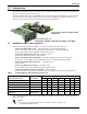
Introduction 1.0 INTRODUCTION The Liebert® IntelliSlot® Web Card family delivers enhanced communications and control to Liebert AC Power and Precision Cooling systems. Liebert IntelliSlot Web cards bring SNMP, Telnet and Web-management capability to many models of Liebert power and cooling equipment. The cards employ an Ethernet network to monitor and manage a wide range of operating parameters, alarms and notifications.
Introduction 1.2 Web Support The Liebert IntelliSlot Web card delivers Web management and control to Liebert equipment. All authorized users on your network will be able to view status information. 1.3 Password Protection Control and configuration capabilities are protected by a username and password combination. Optionally, status information can be password-protected. The default username is “Liebert” and the default password is also “Liebert.
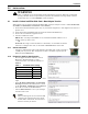
Installation 2.0 INSTALLATION ! WARNING Only a qualified service professional should install these products. Emerson recommends having a Liebert Services representative perform the installation in large UPSs. Contact Liebert Services at 1-800-LIEBERT (1-800-543-2378). 2.1 Install a Liebert IntelliSlot Web Card—Non-Adapter Version Follow these steps to install a Liebert IntelliSlot Web card (non-adapter version—P/N IS-WEBCARD, IS-WEBLB, IS-WEBLBDS, IS-WEBNXL and IS-WEBL). 1.
Installation 2.2 Install a Liebert IntelliSlot Web/485 Card With Adapter ! WARNING Risk of electric shock. Can cause equipment damage, injury or death. Service and maintenance work must be performed only by properly trained and qualified personnel and in accordance with applicable regulations and manufacturers’ specifications.
Configuration Overview 3.0 CONFIGURATION OVERVIEW You may use any of the following interfaces to configure the Web card: Table 4 Configuration interfaces Interface Icon Description Available Functions Connection Methods Terminal Emulation (Serial or TCP/IP) Use terminal emulation software —for example, HyperTerminal. Configuration Serial Cable or TCP/IP Telnet Use a command prompt—enter “telnet” and the IP address or hostname.
Configuration Overview 3.2 Open the Terminal Emulation Interface - Serial Connection To access configuration using terminal emulation software with a serial connection to the Web card: 1. Open a terminal emulation application, such as HyperTerminal. Name To do this: • Click the Start button, then Programs, Accessories, Communications and finally HyperTerminal. 2. In the Connection Description window, enter a name for the connection—for example, GXT2U—then click OK. 3.
Configuration Overview 3.3 Open the Terminal Emulation Interface - TCP/IP Connection To access configuration using terminal emulation software with an Ethernet connection to the Web card: 1. Open a terminal emulation application, such as Name HyperTerminal. To do this: • Click the Start button, then Programs, Accessories, Communications and finally HyperTerminal. 2. In the Connection Description window, enter a name for the connection—for example, GXT2U—then click OK. 3.
Configuration Overview 3.4 Open the Telnet Interface To access configuration using Telnet: 1. Open a Telnet connection on a computer with an Ethernet connection to the Liebert unit. To do this: • Open a command prompt window—click the Start button, then Run. • Enter cmd and click OK. • In the command prompt window that opens, enter telnet followed by a space and the IP address or hostname of the Web card—for example: telnet 192.168.0.125 C:>telnet 192.168.0.125 2.
Configuration Overview 3.5 Open the Web Interface To access configuration using the Web interface: Configure tab 1. Open a Web browser such as Internet Explorer, then enter the IP address or hostname of the Web card in the address bar—e.g., http://192.168.0.125. 2. Click on the Configure tab, shown at right. Configuration Categories appear in the left panel, organized with folder icons. 3. Click on any configuration category, and the Connect To box opens. 4.
System Information 4.0 SYSTEM INFORMATION System Information is optional and identifies the Liebert unit, its location, a contact person and other information about the unit. The default value of each field is “Uninitialized.” NOTE This information also configures the SNMP parameters sysName, sysContact, sysDescr, and sysLocation available using RFC-1213 MIB II.
Network Settings 5.0 NETWORK SETTINGS The IP Network Settings Menu is used to enable network communications with the Web card. Refer to the following sections for detailed step-by-step instructions on each item from this menu: Table 8 Network Settings menu guide Menu item Refer to: 5.1 - Boot/IP Settings page 13 5.2 - Domain Name Server (DNS) Settings page 14 5.3 - Management Protocol page 16 5.4 - Web Server page 21 5.5 - Telnet Server page 26 5.6 - Time (SNTP) Menu page 27 5.
Network Settings 5.1 Boot/IP Settings The Boot/IP Settings Menu is used to set parameters for network access to the Web card. Consult your network administrator for these settings. Terminal Emulation (Serial or TCP/IP Connection) / Telnet Boot/IP Settings Menu ---------------------1: Speed/Duplex Auto 2: Boot mode Static 3: IP Address 192.168.0.125 4: Netmask 255.255.255.0 5: Default Gateway 192.168.0.1 6: DNS Server 0.0.0.0 : Cancel menu level Please select a key ?> To change any parameter: 1.
Network Settings 5.2 Domain Name Server (DNS) Settings The Domain Name Server settings menu configures the servers the Web card will use for hostname resolution. When configured, host addresses for SNMP, Network Time and Email/SMS can be specified in either full Domain Name format or in host-only format, provided that the appropriate Domain Name Suffix is used. The DNS menu is used to set parameters for network access to the Web card. Consult your network administrator for these settings.
Network Settings Web Interface To access the DNS menu through the Web interface: • Click on the Configure tab, then Network Settings in the left panel and finally Edit beneath the table of parameters and descriptions. After making changes, click Save.
Network Settings 5.3 Management Protocol The Management Protocol Menu allows you to enable or disable SNMP and configure management protocols. Consult your network administrator for these settings.
Network Settings Web Interface To access Management Protocol settings through the Web interface: • Click on the Configure tab, then Management Protocol in the left panel and finally Edit in the right panel. After making changes, click Save.
Network Settings 5.3.1 SNMP Communications Menu Use the SNMP Communications Menu to enable authentication traps and view or change communities and trap communities, events and parameters. Refer to Table 12 for details on each menu option, as well as the following sections: • Section 5.3.2 - Display/Modify Communities • Section 5.3.3 - Display/Modify Trap Communities • Section 9.
Network Settings 5.3.2 Display/Modify Communities View devices that have permission to access the Web card, identified by IP address or hostname, read/ write permission and community string. Up to 20 devices may be configured for access. Communities - Example ------------------------10.0.0.5 write 1: 10.0.0.6 write 2: Entry # Codes for editing IP address public1 public1 Access Community (read/write) string dd elete dit Complex lines allowed. e.g.
Network Settings 5.3.3 Display/Modify Trap Communities View devices that are configured to receive notifications from the Web card, identified by IP address or hostname, trap listen port and community string. Up to 20 devices may be configured to receive traps. Trap Communities - Example ------------------------------10.0.0.5 162 public1 1: 2: 10.0.0.6 162 public1 Entry # Codes for editing IP address Port to Community receive traps string dd elete dit Complex lines allowed. e.g.
Network Settings 5.4 Web Server Use the Web Server Menu to configure access to the card through the Web interface. Consult your network administrator if needed. 5.4.
Network Settings 5.4.2 Install Security Certificates - Internet Explorer 6 or earlier If you use Internet Explorer 6 or an earlier version and select HTTPS as the operation mode of the Web server (see 5.4.1 - Specify Web Server Settings), follow these instructions to install a security certificate. • Open Internet Explorer and enter https:// followed by the IP address or hostname of the Web card—for example, https://192.168.0.125—in the address bar. The following message appears.
Network Settings • In the Certificate window, click the Install Certificate button, as shown below. Install Certificate • The Certificate Import Wizard opens. Click Next. Automatically select... • Click on Automatically select the certificate store based on the type of certificate, then click Next. • The final Wizard window appears with a message that the process is complete. Click Finish. • A confirmation box appears with a message that the import was successful. Click OK.
Network Settings 5.4.3 Install Security Certificates - Internet Explorer 7 or later If you use Internet Explorer 7 or later and select HTTPS as the operation mode of the Web server (see 5.4.1 - Specify Web Server Settings), follow these instructions to install a security certificate. To do this: • Open Internet Explorer and enter https:// followed by the IP address or hostname of the Web card—for example, https://192.168.0.125—in the address bar. The following message appears.
Network Settings • In the Certificate window, click the Install Certificate button, as shown below. Install Certificate • The Certificate Import Wizard opens. Click Next. Automatically select... • Click on Automatically select the certificate store based on the type of certificate, then click Next. • The final Wizard window appears with a message that the process is complete. Click Finish. • A confirmation box appears with a message that the import was successful. Click OK.
Network Settings 5.5 Telnet Server Telnet Server Menu ------------------1: Telnet Server Use the Telnet Server Menu to enable or disable access to the Web card through a Telnet interface. 'enabled' : Cancel menu level Please select a key ?> Terminal Emulation (Serial or TCP/IP Connection) / Telnet To change this setting: 1. Choose IP Network Settings from the Main Menu, then Telnet Server. 2.
Network Settings 5.6 Time (SNTP) Menu This permits setting time options—how often the Web card synchronizes with the Time Server, which Time Server to use for synchronization and which the Time Zone the Web card is operating in. Time Server Menu ------------------1: SNTP Time Sync Rate 2: Time Server 3: Time Zone Hourly time.nist.gov (GMT) UTC : Cancel menu level Please select a key ?> Terminal Emulation (Serial or TCP/IP Connection) / Telnet To change this setting: 1.
Network Settings 5.7 Change Username / Password The Web card is designed for two types of access, each with a default user name and password. For security, be sure to change the default password.
Network Settings 5.8 Reset Authentication to Factory Defaults You may reset the Administrator and General User usernames and passwords to the factory defaults. If you forget your username or password, you may reset them using a serial configuration cable connection (see Section 2.1.1 or 2.2.1 - Connect the Cable), which provides direct access to the card without a username or password. To enter a new username and password, see 5.7 - Change Username / Password.
Messaging 6.0 MESSAGING The Messaging menu is used to set up e-mail and text message notifications from the Web card. Terminal Emulation (Serial or TCP/IP Connection) / Telnet Messaging Menu --------------1: Email 'disabled' 2: SMS 'disabled' 3: Email Configuration 4: SMS Configuration To access these options: : Cancel menu level 1. Choose Messaging from the Main Menu. 2. Select an option, then use the following guide to make changes.
Messaging 6.1 E-Mail Configuration Setting up event notifications to be sent via e-mail involves two steps: enabling the function, then specifying the parameters. Terminal Emulation (Serial or TCP/IP Connection) / Telnet To activate and set up e-mail messages: 1. Choose Messaging from the Main Menu, then Email.
Messaging 6.2 SMS Configuration Setting up event notifications for SMS text messages involves two steps: enabling the function, then specifying the parameters. Terminal Emulation (Serial or TCP/IP Connection) / Telnet To activate and set up SMS messages: 1. Choose Messaging from the Main Menu, then SMS.
Messaging 6.3 Customize Messages Both e-mail and SMS text messages may be customized to include items such as the IP address or hostname, event name and a link to the Web card in the body of the message.
Factory Settings 7.0 FACTORY SETTINGS The Factory Settings menu allows you to restore factory default settings and offers other options that may vary by the Liebert unit where the card is installed. Refer to the following sections for details: • • • • 7.1 - Reset to Factory Defaults 7.2 - Advanced Communication Settings 7.3 - Agent Event Log - Liebert NXL, Liebert XDP with Liebert iCOM & Liebert CRV 7.4 - Support Information - Liebert NXL, Liebert XDP with Liebert iCOM & Liebert CRV • 7.
Factory Settings 7.2 Advanced Communication Settings The Advanced Communication Settings menu offers the following options: • 7.2.1 - Local Node Settings for Multiple Cards • 7.2.2 - Managed Device Settings - Liebert NXL, Liebert XDP with Liebert iCOM & Liebert CRV • 7.2.3 - Router Settings - Liebert NXL, Liebert XDP with Liebert iCOM & Liebert CRV 7.2.
Factory Settings 7.2.2 Managed Device Settings - Liebert NXL, Liebert XDP with Liebert iCOM & Liebert CRV Use the Managed Device Settings menu for connection settings for the Liebert NXL, Liebert XDP with Liebert iCOM or Liebert CRV.
Factory Settings 7.
Factory Settings 7.5 Realtime Information - Liebert NXL, Liebert XDP with Liebert iCOM & Liebert CRV Use this menu to display realtime information for the following Precision Cooling units: • Liebert NXL • Liebert XDP with Liebert iCOM • Liebert CRV : Cancel menu level Please select a key ?> Terminal Emulation (Serial or TCP/IP Connection) / Telnet To view realtime information for the units listed above: 1. Choose Factory Settings from the Main Menu, then choose Realtime Information. 2.
Monitor and Control Functions - Web Only 8.0 MONITOR AND CONTROL FUNCTIONS - WEB ONLY Web Interface Only The Web interface allows you to monitor and control the Liebert equipment where the Web card is installed, in addition to configuration capabilities presented in previous sections. 8.1 Monitoring Liebert Equipment To view monitoring data through the Web interface: • Open the Web interface (if needed, see 3.5 - Open the Web Interface). • Click on the Monitor tab if needed.
Monitor and Control Functions - Web Only 8.2 Controlling Liebert Equipment To perform Control operations through the Web interface: • Open the Web interface (if needed, see 3.5 - Open the Web Interface). • Click on the Control tab, as shown in the following example. Control tab Control Operations Click to view in right panel • Control Operations categories appear at bottom left, organized with folder icons and showing the available Control functions.
Monitor and Control Functions - Web Only 8.3 Event Log NOTE For the Liebert XDP with Liebert iCOM and Liebert CRV, the Web interface has a Data/Logs tab instead of the Event Log tab. For details, refer to 8.4 - Data/Logs Tab (Liebert XDP with Liebert iCOM & Liebert CRV). The Event Log tab allows viewing events stored in the Web card’s history. This history is gathered only when the Web card is installed and communicating properly with the device.
Monitor and Control Functions - Web Only 8.4 Data/Logs Tab (Liebert XDP with Liebert iCOM & Liebert CRV) The Data/Logs tab offers the following features for the Liebert XDP with Liebert iCOM and Liebert CRV. Table 24 Data/Logs tab features (Liebert XDP with Liebert iCOM & Liebert CRV) Feature Description For details, see: Agent Log of events for the card 8.4.1 - Event Log Agent SNMP Capabilities Events and parameters available for this Liebert unit 8.4.
Monitor and Control Functions - Web Only 8.4.1 Event Log Agent The Event Log Agent allows viewing events stored in the Web card’s history. This history is gathered only when the Web card is installed and communicating properly with the device. The history is stored in descending chronological order; Page 1 Item 1 contains the most recent event. The list of events includes: 1.
Monitor and Control Functions - Web Only 8.4.2 Events and Parameters You may view a list of all supported SNMP events and parameters for the Liebert equipment through the Web interface. To view this data: • Click on the Data/Logs tab at the top of the window. • Click on Events (or Parameters) in the left panel under SNMP Capabilities. • The events or parameters are listed in the right panel. The example below shows a list of Events.
Support Information 9.0 SUPPORT INFORMATION Support data includes identifying information for the Web card, as well as events and parameters available for the Liebert equipment. 9.1 View Web Card Information Identifying information for the Web card may be viewed through any interface and includes the MAC address, model and part number, serial number and firmware version. Terminal Emulation (Serial or TCP/IP Connection) / Telnet To view Web card information: 1.
Support Information 9.2 Events and Parameters You may view a list of all supported events and parameters for the Liebert equipment through any interface. Depending on the Liebert IntelliSlot Web card, the list might include SNMP and Modbus. Terminal Emulation (Serial or TCP/IP Connection) / Telnet To view this data: • Choose IP Network Settings from the Main Menu. • Choose Management Protocol, then SNMP Communications.
Introduction APPENDIX A - FIRMWARE UPDATES A.1 INTRODUCTION Liebert’s IntelliSlot® cards may be updated to take advantage of the latest release of the firmware with enhanced features, compatibility with new units or service patches. Upgraded firmware may be downloaded with a browser, such as Internet Explorer. Emerson maintains firmware upgrades on its Web site, www.liebert.com/downloads. Emerson manufactures various types of network cards for Liebert products.
Connect to the Card - Terminal Emulation, Telnet or Web Interface A.2 CONNECT TO THE CARD - TERMINAL EMULATION, TELNET OR WEB INTERFACE Upgrading the firmware requires connecting to the card with one of these interfaces. A.2.1 Open the Terminal Emulation Interface - Serial Connection To connect to the card using terminal emulation software with a serial connection to the Web card: 1. Open a terminal emulation application, such as HyperTerminal.
Connect to the Card - Terminal Emulation, Telnet or Web Interface A.2.3 Open the Telnet Interface To connect to the card using Telnet: 1. Open a Telnet connection on a computer with an Ethernet connection to the Liebert unit. To do this: • Open a command prompt window—click the Start button, then Run. • Enter cmd and click OK. • In the command prompt window that opens, enter telnet followed by a space and the IP address of the Web card—for example: telnet 192.168.0.125 C:>telnet 192.168.0.125 2.
Preparing to Update Liebert IntelliSlot Firmware A.3 PREPARING TO UPDATE LIEBERT INTELLISLOT FIRMWARE A.3.1 Requirements to Update the Liebert IntelliSlot Card’s Firmware Make sure you have the following before starting the update: • Firmware upgrade downloaded from the Liebert Web site (see A.3.3 - Download the Firmware Upgrade File to the Computer) • A computer running Internet Explorer 5.
Preparing to Update Liebert IntelliSlot Firmware A.3.3 Download the Firmware Upgrade File to the Computer NOTE Turn off the power management on your PC or laptop before beginning the update to ensure that communication will not be disrupted during the process. To download the upgrade file: 1. Open a Web browser, such as Internet Explorer (5.5 or newer). 2. Navigate to the Liebert Web site, www.liebert.com/downloads. 3. Choose the firmware upgrade for your card from the selections on the Web page (see A.3.
Updating the Firmware - HTTP (Web) Method A.4 UPDATING THE FIRMWARE - HTTP (WEB) METHOD Follow these steps to install the firmware upgrade using the HTTP (Web) method. This method is available through the Web interface only and requires an Ethernet connection to the Web card. A.4.1 Install the Firmware Upgrade NOTE Turn off the power management on your PC or laptop before beginning the update to ensure that communication will not be disrupted during the process.
Updating the Firmware - TFTP (HyperTerminal, Telnet, Web) Method A.5 UPDATING THE FIRMWARE - TFTP (HYPERTERMINAL, TELNET, WEB) METHOD Follow these steps to update the firmware using the TFTP method. This method is available through the terminal emulation, Telnet and Web interfaces with an Ethernet connection to the Web card. NOTE This method includes a time-sensitive operation requiring expeditious location of the upgrade files downloaded in A.3.3 - Download the Firmware Upgrade File to the Computer.
Updating the Firmware - TFTP (HyperTerminal, Telnet, Web) Method Begin the Upgrade Process 11. When ready to begin the update, choose Initiate TFTP Firmware Update. 12. Open the TFTP application and start TFTP. Ensure that all settings are ready to transfer the file, including the location of the upgrade file. Refer to your TFTP user manual for more details. 13. Return to the terminal emulation/Telnet screen. At the confirmation message prompt, enter y (yes) to confirm your choice.
Updating the Firmware - TFTP (HyperTerminal, Telnet, Web) Method A.5.2 TFTP Method - Web Interface To update the Liebert IntelliSlot card firmware using the TFTP method with a Web interface: Open a Connection to the Card 1. Open a connection to the Liebert IntelliSlot card (if needed, see instructions in A.2.4 - Open the Web Interface). 2. Click on the Configure tab, then TFTP in the left panel. Configure tab Edit TFTP 3. Enter the Administrator username and password (both are case-sensitive): a.
Updating the Firmware - TFTP (HyperTerminal, Telnet, Web) Method Begin the Upgrade Process 8. Open the TFTP application and start TFTP. Ensure that all settings are ready to transfer the file, including the location of the upgrade file. Refer to your TFTP user manual for more details. 9. Return to the Web interface. 10. When ready to begin the download, click the Update Firmware button. Update Firmware 11. During the update, the window displays a progress bar, as shown below left.
Updating the Firmware - Xmodem (Serial) Method A.6 UPDATING THE FIRMWARE - XMODEM (SERIAL) METHOD Follow these steps to update the firmware using the Xmodem (serial) method. This method works through the Web card’s serial port, employing terminal emulation software, such as HyperTerminal. NOTE This method includes a time-sensitive operation requiring expeditious location of the upgrade files downloaded in A.3.3 - Download the Firmware Upgrade File to the Computer.
Updating the Firmware - Xmodem (Serial) Method Download the First Firmware Update File 12. After changing the communication rate to 115200 bps, press Enter to resume the firmware update. After you press Enter, HyperTerminal displays Cs as it counts down the time remaining to locate and begin transferring the upgrade files. NOTE After you begin the initialization process in Step 12, you must complete Steps 13 through 15 within 60 seconds.
Updating the Firmware - Xmodem (Serial) Method Complete the Upgrade and Restore Communication Rate 22. Choose 9600 bps from the menu, shown below left. 23. From the HyperTerminal menu, click on Call, then choose Disconnect (this will not close the HyperTerminal connection to the card). 24. In the HyperTerminal menu bar, click on File, then choose Properties. 25. Click on the Connect To tab and click the Configure button. This opens Port Settings tab in the COM1 Properties window, as shown below right. 26.
Updating the Firmware - Xmodem (Serial) Method Notes A14
Ensuring The High Availability Of Mission-Critical Data And Applications. Emerson Network Power, the global leader in enabling business-critical continuity, ensures network resiliency and adaptability through a family of technologies—including Liebert power and cooling technologies—that protect and support business-critical systems. Liebert solutions employ an adaptive architecture that responds to changes in criticality, density and capacity.