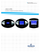
Precision Cooling For Business-Critical Continuity™ Liebert® iCOM™ User Manual - Intelligent Communications & Monitoring
TABLE OF CONTENTS 1.0 INTRODUCTION . . . . . . . . . . . . . . . . . . . . . . . . . . . . . . . . . . . . . . . . . . . . . . . . . . . . . . . . . .1 1.1 Features . . . . . . . . . . . . . . . . . . . . . . . . . . . . . . . . . . . . . . . . . . . . . . . . . . . . . . . . . . . . . . . . . . . 1 2.0 LIEBERT ICOM DISPLAY COMPONENTS AND FUNCTIONS . . . . . . . . . . . . . . . . . . . . . . . . . . .2 2.1 Navigating Through the Liebert iCOM Menus . . . . . . . . . . . . . . . . . . . . . . . . . . .
3.9 Next Maintenance Calculation . . . . . . . . . . . . . . . . . . . . . . . . . . . . . . . . . . . . . . . . . . . . . . . . 37 3.9.1 Calculation of Next Maintenance and Diagnostics. . . . . . . . . . . . . . . . . . . . . . . . . . . . . . . . . . 37 4.0 TEAMWORK . . . . . . . . . . . . . . . . . . . . . . . . . . . . . . . . . . . . . . . . . . . . . . . . . . . . . . . . . . .39 4.1 Teamwork Modes . . . . . . . . . . . . . . . . . . . . . . . . . . . . . . . . . . . . . . . . . . . . . . . . .
FIGURES Figure 1 Figure 2 Figure 3 Figure 4 Figure 5 Figure 6 Figure 7 Figure 8 Figure 9 Figure 10 Figure 11 Figure 12 Figure 13 Figure 14 Figure 15 Figure 16 Figure 17 Figure 18 Figure 19 Figure 20 Figure 21 Figure 22 Figure 23 Figure 24 Figure 25 Figure 26 Figure 27 Figure 28 Figure 29 Figure 30 Figure 31 Liebert iCOM components . . . . . . . . . . . . . . . . . . . . . . . . . . . . . . . . . . . . . . . . . . . . . . . . . . . . . . . . . 1 Liebert iCOM display components . . . . . . . . . . . . . . .
TABLES Table 1 Table 2 Table 3 Table 4 Table 5 Table 6 Table 7 Table 8 Table 9 Table 10 Table 11 Table 12 Table 13 Table 14 Table 15 Table 16 Table 17 Table 18 Table 19 Table 20 Table 21 Table 22 Table 23 Table 24 Table 25 Table 26 Table 27 Table 28 Table 29 Table 30 Table 31 Table 32 Table 33 Keyboard icons and functions. . . . . . . . . . . . . . . . . . . . . . . . . . . . . . . . . . . . . . . . . . . . . . . . . . . . . . . 3 User menu icons . . . . . . . . . . . . . . . . . . . . . . . . . . . . . .
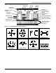
Introduction 1.0 INTRODUCTION The Liebert iCOM™ control offers the highest capabilities in unit control, communication and monitoring of Liebert mission-critical cooling units. Liebert iCOM may be used to combine multiple cooling units into a team that operates as a single entity, enhancing the already-high performance and efficiency of Liebert’s units. Liebert iCOM is available as a factory-installed assembly or may be retrofitted on existing products with SM, AM or AG controls.
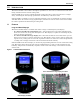
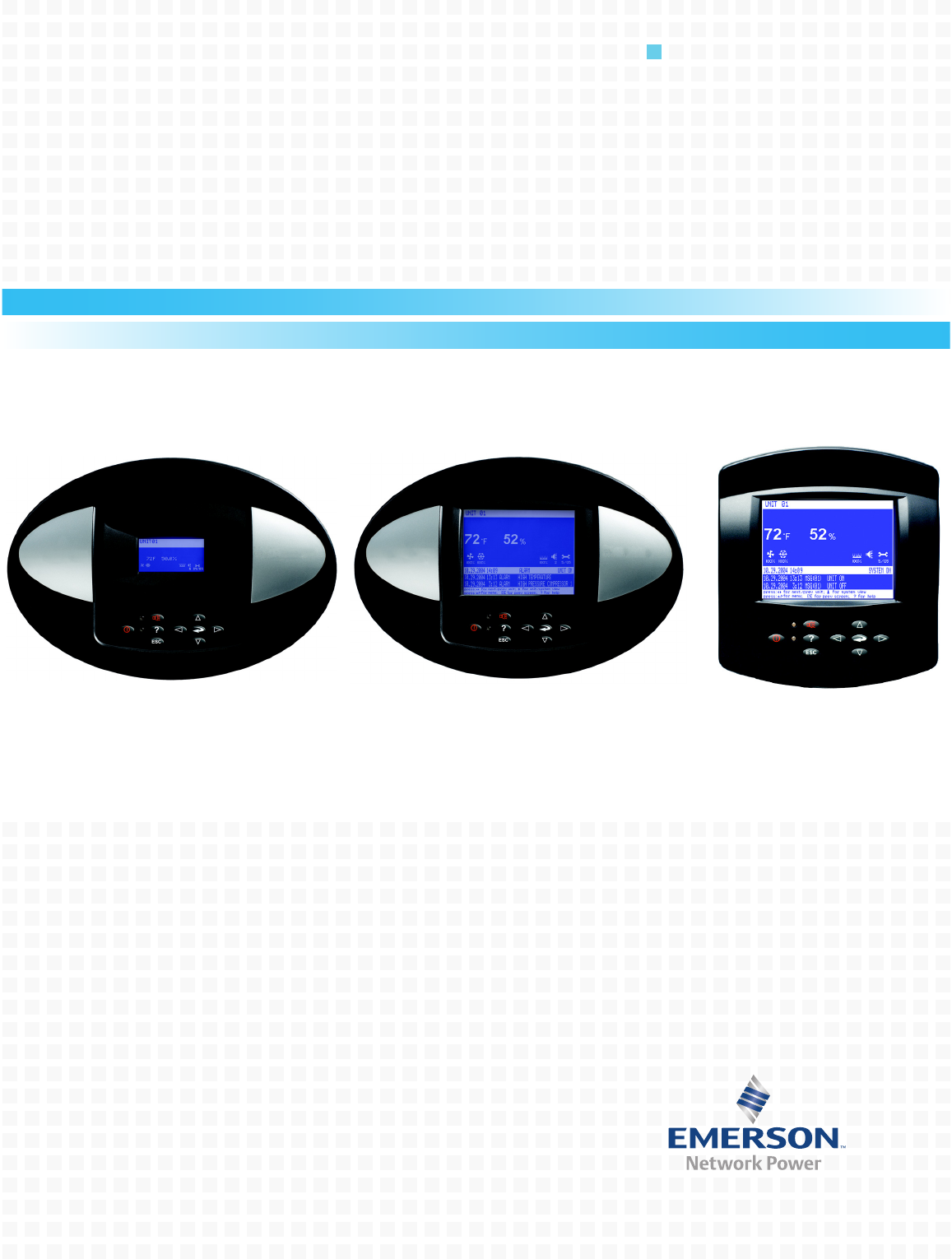
Liebert iCOM Display Components and Functions 2.0 LIEBERT ICOM DISPLAY COMPONENTS AND FUNCTIONS The small and the large display have a common key layout, as shown in Figure 2. Figure 2 Liebert iCOM display components Liquid Crystal Display LED Status Indicators (top LED is red or flashing red; bottom LED is green or amber) ? ESC Large Liebert iCOM Display shown - Keypad and LEDs are identical on all displays.
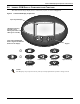
Liebert iCOM Display Components and Functions Table 1 Icon ? ESC Keyboard icons and functions Key Name Function On/Off Key Controls the operational state of the cooling unit. Alarm Key Silences an alarm. Help Key Accesses integrated help menus. ESCape Key Returns to the previous display view. Enter Key Confirms all selections and selects icons or text. Increase Key (Up Arrow) Moves upward in a menu or increases the value of a selected parameter.
Liebert iCOM Display Components and Functions Figure 3 Status menu, large display, graphical view System or Unit # view Temperature Setpoint Humidity Setpoint Humidity Sensor Reading Supply Air Temperature Percent Hot Water Heating Percent Electric Heating Temperature Sensor Reading Evaporator Fan Speed Percent Cooling Free-Cooling Percentage Percent Dehumidifying Percent Humidifying System (or Unit) On/Off Next Maintenance Date and Time Figure 4 Most Recent Alarms (Date, Time, Unit, Description)
Liebert iCOM Display Components and Functions 2.1 Navigating Through the Liebert iCOM Menus Liebert iCOM shows icons and text for monitoring and controlling your Liebert cooling units or network of cooling units. The number of icons and amount of text shown depends on the display size. 2.1.1 Control Interface When the buttons on the Liebert iCOM control have not been pressed for a short period, the display backlight turns off.
Liebert iCOM Display Components and Functions 2.1.3 Entering a Password To change the value of a parameter in a menu, you must first enter the password for that menu. The User, Service and Advanced menus each has a unique password to prevent unauthorized changes. The User menu password is 1490; the Service menu password is 5010. NOTE Entering the Service menu password permits access to both the User and Service menus. To enter a password: 1. Navigate to the menu that contains the parameter to be changed.
Liebert iCOM Display Components and Functions Figure 6 Menu tree—Large display, stand-alone Unit 1 will be displayed in the top left corner of the screen.
Liebert iCOM Display Components and Functions 2.1.4 Viewing Multiple Units with a Networked Large Display When you first wake up the control, press the Esc key to return to the System view Status menu. This view shows an average of all the units on the network and any alarms present. To view a specific unit on the network, press either the enter key or down arrow key. When you do this, you will see the word System in the top left of the screen change to a unit number.
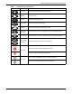
Liebert iCOM Display Components and Functions Figure 8 User menu icons User Menu password: 1490 Table 2 User menu icons Icon Name °C / °F % RH SET EVENT LOG SET ALARMS ! Description Available On Display Setpoints View and change temperature and humidity setpoints Small & Large Spare Part List Displays the various part numbers of the components/parts in the cooling unit Large Event Log Contains last 400 events Small & Large Graphics Displays temperature and humidity graphs Small & La
Liebert iCOM Display Components and Functions Table 2 User menu icons (continued) Icon Name Description Available On Display Sleep Mode Allows setback settings for non-peak operation Small & Large Service Contact Info Contains key contact information for local Small & Large service, including names and phone numbers 12 9 3 6 10
Liebert iCOM Display Components and Functions Figure 9 Service menu icons Service Menu password: 5010 Table 3 Service menu icons Icon °C / °F % RH SET WELLNESS Description Available On Display Setpoints To view and change temperature and humidity setpoints Small & large Unit Diary Shows all entered program changes and maintenance performed on the unit Large Standby Settings/ Lead-Lag Allows lead/lag setup when multiple units are connected Small & large Maintenance/ Wellness Settings All
Operation 3.0 OPERATION The Liebert iCOM display for your Liebert cooling unit features an easy-to-use, menu-driven liquid crystal display (LCD). All unit settings and parameters can be viewed and adjusted through three menus: User, Service and Advanced. All active alarms are displayed on the LCD and annunciated. The control is shipped from the factory with default selections for all necessary settings. Adjustments can be made if the defaults do not meet your requirements.
Operation Autorestart When there is a loss of power to the cooling unit and power comes back, the unit will return to its previous operating status—on if it was on before the power off, off if it was off. When power returns, the autorestart time—time-selectable: Single Unit Auto Restart (Service Menu, Options Setup)—controls the start of the unit. The autorestart time runs in a loop, starting the next unit each time when elapsed, starting with Unit # 1.
Operation 3.1.3 General Compressor Requirements Low-Pressure Time Delay When the compressor starts, the low-pressure input is ignored for a selected period of time based on the setting of the Low Pressure Alarm Delay (Service Menu, Options Setup). This time is usually set to 3 minutes on air-cooled units, and to 0 or 1 minute on water cooled units. When this time is expired, a second timer starts to operate if the low-pressure input is active.
Operation Digital Scroll High Temperature A protective maximum operating compressor temperature limit is imposed on units with digital scroll compressor(s) with thermistor. Once the digital scroll temperature reaches the maximum temperature threshold, the compressor will be locked out for at least 30 minutes and an alarm will be annunciated. If after 30 minutes the temperature has cooled to a safe operating temperature, the compressor will resume operation.
Operation 3.2 Motorized Ball Valve in Digital Scroll Units On digital scroll units, discharge pressure is controlled by a motorized ball valve. During unloaded operation, pressure changes during each digital cycle could cause a pressure-controlled water regulating valve to open and close an excessive number of times. The motorized ball valve is designed to maintain a consistent peak discharge pressure on Water/Glycol Cooled Digital Compressor Systems.
Operation 3.3 Temperature Control—Single Source Cooling (No Extra Cooling Coil) 3.3.1 Temperature Proportional Band The control uses the temperature proportional band to determine which operation to perform (cooling/heating) and how intensely to perform it. The Temperature Proportional Band is a user-defined range that is divided into two equal parts for cooling and heating. The Temperature Setpoint is between these two equal parts.
Operation 3.3.2 Compressor Control Depending on the type of Liebert air conditioning unit you have your unit may contain one or two compressors with or without unloaders. Compressor Proportional Bands One Single-Step Compressor Without Unloaders—One-Step One single-step compressor, Cool 1, is started at 100% call for cooling from the temperature proportional band and stopped at 0% (see Figure 12).
Operation Two Compressors With Unloaders—Four-Step The first two-step compressor is started unloaded at 33% calculated output from the temperature proportional band and stopped at 17%. At 80% Compressor 1 will be loaded, at 70% unloaded. The second compressor starts unloaded at 63% and stops at 47%. At 100%, Compressor 2 will be loaded, at 90% unloaded (see Figure 14).
Operation Digital Scroll Compressors A compressor with a suction cutoff unloader can only modulate its capacity between two distinct levels: fully loaded and half loaded. A digital scroll compressor can modulate its capacity anywhere between 10-100%. This variable capacity modulation allows cooling units to control an environment more precisely. Digital scroll capacity modulation is achieved by energizing and de-energizing a solenoid valve on the compressor.
Operation 3.3.3 Chilled Water Control The chilled water control valve is adjusted proportionally as the temperature control varies the requirement for cooling from 0% to 100%. Units with the optional variable speed drive (VSD) control the fan speed in a similar manner, except that the minimum fan speed is 60% when the cooling requirement is less than 60%. Also, the fan is operated at 100% on a call for any heating and/or humidification.
Operation The Value setting is the factory default setting on free-cooling and dual cooling units. If the temperature difference between the second source cooling fluid parameter, Free-cooling Fluid Temperature (User Menu, Sensor Data) and room air is equal to or greater than the adjustable DT Between Room Air / FC Fluid (Service Menu, Setpoints) value, then the second source cooling fluid will be used to provide at least partial cooling (delta T between room and glycol = true).
Operation GLYCOOL™ Cooling—Free-Cooling When GLYCOOL cooling is available, the temperature control will calculate a total cooling requirement of 200% rather than 100%. Assuming that full GLYCOOL capacity is available, the GLYCOOL valve opens proportionally as the requirement for cooling rises from 0 to 100%. If more than 100% cooling is required, then the compressors are activated at 150% and 200% respectively (133%, 163%, 180% and 200% for a four-step system).
Operation Figure 19 Three-stage heating Temp Setpoint: 70°F Proportional Band: 8°F Deadband: 2°F Heat 3 Heat 2 On On 65 -100 % Heating 66 Heat 1 On 67 Heat 3 Off 68 Heat 2 Off ½ Proportional Band Decreasing Temperature 24 ½ Deadband 69 Heat 1 Off 70 0% Heating
Operation 3.5.2 SCR Reheat SCR reheat is a type of electric reheat that provides tighter temperature control than staged electric reheat. SCR reheat capacity modulation is achieved by pulsing the reheat On and Off. Full capacity is achieved by constantly energizing the reheat. Units equipped with SCR reheat can operate in Tight or Standard mode. By default, cooling units with SCR reheat are factory-set to operate in Tight mode.
Operation Standard Mode In Standard mode, the SCR reheat operates only when the Temperature Proportional Band calls for heating. SCR reheat output is adjusted proportionally as the Temperature Proportional Band varies the requirement for heating from 0% to -100%. Compressors operate only when there is a call for cooling as described in 3.3.2 - Compressor Control. Figure 21 illustrates how SCR reheat operates when SCR Control Type is set to Standard mode.
Operation 3.6 Humidity Control The control uses the humidity proportional band to determine which operation to perform (dehumidification/humidification) and how intensely to perform it. The Humidity Proportional Band is a user defined range that is divided into two equal parts for dehumidifying and humidifying. The Humidity Setpoint is located between these two equal parts.
Operation 3.6.1 Humidification Infrared Humidifier There are two types of infrared humidifiers: small pan (IFS) and large pan (IFL). The operating mode of each is similar, however, some of the variables or timings differ. Infrared humidifiers are started at 100% humidification request, and stopped at 0%. Infrared humidifiers cannot be driven in proportional mode.
Operation 3.6.2 Dehumidification The Dehumidification Enable parameter (Service Menu, Options Setup) allows for enabling/disabling the dehumidification function. A call for dehumidification is calculated in the same way as a cooling request. The components (valves, compressors) will follow this dehumidification request as soon as it is higher than the request for cooling. Dehumidification Low Limit Low Limit 1 and Low Limit 2 are used to avoid overcooling a room during dehumidification.
Operation Reheat During Dehumidification Hot gas reheat or hot water reheat will start as described in 3.5 - Temperature Control—Reheat, when the temperature decreases during the dehumidification process. The parameter Electric Reheat Operation defines how the heaters react in case the temperature decreases during the dehumidification process. This parameter does not impact SCR reheat operation.
Operation Intelligent – If Intelligent Control is selected, the return air temperature/humidity is controlled at or near the setpoint. The percent temperature/humidity adjustment required is calculated based on logic that is programmed into the control. These rules simulate the actions that a human operator would take if manually controlling the system. This control type is commonly selected on chilled water units.
Operation 3.7.3 Supply Limit—Optional Chilled water units may be ordered with an additional sensor for monitoring the supply air temperature. This sensor maintains the minimum air temperature under a raised floor to help prevent condensation from forming. In order to avoid supply temperatures that are too low, the Supply Limit can influence the opening of three-point or analog actuators or the output of analog values.
Operation 3.7.5 User Inputs / Customer Inputs The user can connect and specify up to four inputs depending on unit configuration. The user inputs/customer inputs are digital inputs that influence the operating mode of the unit depending on the selection. The customer input configuration settings are in the Service menu under Set Alarms, Screen 2 of 7. The choices for the customer inputs are shown in Table 7 along with their associated reaction.
Operation 3.7.6 Event Types and Properties Liebert iCOM events are used to inform the user of cooling unit operational status. All events are recorded in the Event Log, which is in the User Menu. The user can change the type (alarm, warn, message) and time delay of some events and can also enable or disable some events. These event settings are in the Service Menu under Set Alarms, pages 3 to 7. If an event has a safety function (high pressure, low pressure, main fan overload, etc.
Operation Table 8 Possible event settings—some events not available in all units Event MAIN FAN OVERLOAD LOSS OF AIRFLOW CLOGGED FILTERS HIGH ROOM TEMP LOW ROOM TEMP HIGH ROOM HUM LOW ROOM HUM HIGH TEMP SENSOR A LOW TEMP SENSOR A HIGH HUM SENSOR A LOW HUM SENSOR A COMP 1 OVERLOAD COMP 2 OVERLOAD COMP 1 HIGH PRESSURE COMP 2 HIGH PRESSURE COMP 1 LOW PRESSURE COMP 2 LOW PRESSURE COMP 1 PUMPDOWN FAIL COMP 2 PUMPDOWN FAIL DIG SCROLL1 HIGH TEMP DIG SCROLL2 HIGH TEMP EL HEAT HIGH TEMP WORKING HRS EXCEEDED SMOKE
Operation 3.8 POSSIBLE EVENT NOTIFICATIONS Table 9 lists alarms and warnings that may occur in a cooling unit. When any of these occur, they will appear on the Liebert iCOM Status menu and will be recorded in the Liebert iCOM Event log.
Operation 3.9 Next Maintenance Calculation The next maintenance calculation, as well as the included diagnostics feature, will help run the cooling unit optimally to ensure minimum component stress resulting in maximum reliability. The diagnostics will help the service engineer evaluate the unit’s operation, reading back operational data since the last maintenance. 3.9.
Operation Parameters for Next Maintenance Calculation General Maintenance Settings • Maintenance Frequency—can be set as one to 12 months or to zero, which disables maintenance calculation • Max. Bonus—increases the time to next maintenance with the set value, if all components run optimally (number of starts, average running time) • Max.
Teamwork 4.0 TEAMWORK Unit-2-Unit (U2U) Communications via a private network will allow the following functions to be placed into operation when the requirement exists. The user must install the correct hardware (see 5.0 - Installing a Liebert iCOM Unit-to-Unit Network) and properly program the units for the selected functionality. The Liebert iCOM network can perform the following functions: The Teamwork Mode functions allow for multiple stages of cooling/heating and humidification/dehumidification.
Teamwork The number of available units is calculated like: • In non-standby configuration: all units with fan on • In typical standby function (no cascade): all units with fan on • In cascade mode: all units that could operate (no alarm, which forces the unit to switch off, unit not switched off, etc.) NOTE 1. Proportional actuators (chilled water valve, free-cooling actuator) are driven in parallel in all units. 2.
Teamwork 4.1.4 Teamwork Mode 2 Teamwork Mode 2 is designed to prevent units within a group from working against each other or “fighting.” It is best applied in large rooms with unbalanced heat loads. In Teamwork Mode 2, all parameters are shared equal to Mode 1, and Unit #1 averages all of the available unit sensor readings on the network to define whether there is a cooling, heating, dehumidification or humidification request.
Installing a Liebert iCOM Unit-to-Unit Network 5.0 INSTALLING A LIEBERT ICOM UNIT-TO-UNIT NETWORK Connecting multiple Liebert iCOM-controlled cooling units in an Ethernet Unit-to-Unit (U2U) network enables the units to work together to achieve efficient cooling and humidity control of the conditioned space.
Installing a Liebert iCOM Unit-to-Unit Network 5.3 Wiring for Unit-to-Unit Communications—U2U Cooling units come from the factory-wired for stand-alone operation. Liebert iCOM U2U Ethernet Network The Liebert iCOM U2U network must be isolated from other network traffic. The network switch(es) that connect Liebert iCOM controls need to be dedicated to supporting only Liebert iCOM communication. The U2U network cannot be connected to the building or IT network.
Installing a Liebert iCOM Unit-to-Unit Network 5.3.1 Wiring a Liebert iCOM U2U Network Small Displays Two cooling units, each with a small display: To network two cooling units, each with a small display, connect a crossover CAT5 cable between the P64 connectors on each cooling unit’s Liebert iCOM input/output board. A network switch is not needed (see Figure 24).
Installing a Liebert iCOM Unit-to-Unit Network Figure 25 Wiring a small display for stand-alone operation Small Graphics Display On Unit Accent Stand-Alone Unit P66 P67 CAN CAN 6-Wire Cable P61 P63 E5 P67 P64 P18 P65 P40 P32 P66 P7 P13 P12 P11 P8 P33 iCOM Microprocessor and I/O Board P34 P38 P39 P53 TB1 P51 P52 E1 E2 E3 E4 P43 P35 P36 P54 P22 P4 Unit Electronics Compartment 182964 Page 1 Rev.
Installing a Liebert iCOM Unit-to-Unit Network Figure 27 Wiring a large display for stand-alone operation Large Graphics Display On Unit Accent Stand-Alone Unit LiebertSupplied Crossover Coupler (F-F) P64 P66 P67 U2U CAN CAN 8-Wire Crossover Ethernet Cable (Red) 6-Wire Cable P63 P64 E5 P67 P61 P65 P40 P32 P18 P66 P7 P13 P12 P11 P8 P33 iCOM Microprocessor and I/O Board P34 P38 P39 P53 TB1 E1E2 E3E4 P4 P51 P52 P43 P35 P36 P54 P22 182964 Page 2 Rev.
Installing a Liebert iCOM Unit-to-Unit Network Figure 29 Liebert iCOM input-output control board P65 P61 P64 (RJ-45 Jack) P63 P67 P66 Liebert vNSA The Liebert vNSA is designed to connect multiple Liebert iCOM control devices. The Liebert vNSA contains either one or two powered industrial rail switches. An optional remote large display can be attached to the front door as well. All models have a power supply that requires connection to a single phase 120V or 240VAC power source.
Installing a Liebert iCOM Unit-to-Unit Network Figure 30 Liebert vNSA with optional remote large display 3.298" (84mm) 12" (305mm) 14.25" (362mm) DPN001136 Rev. 0 5.4 External Communications—Building Management Systems, Liebert SiteScan® Liebert iCOM is capable of communicating with external monitoring systems, such as Building Management Systems (BMS), Network Monitoring Systems (NMS), Liebert's SiteScan® Web system and others.
Mounting a Large Display on a Wall 6.0 MOUNTING A LARGE DISPLAY ON A WALL 6.0.1 Location Considerations Consider these factors before beginning work on a wall-mount installation: • Power supply—Liebert iCOM requires an electricity source. A factory-supplied 120VAC transformer connects to the back of the large display.
Mounting a Large Display on a Wall Figure 31 Liebert iCOM display dimensions U2U CAT5 Cable 150ft. (45.7m) maximum to be field-supplied and field-connected to switch or hub AC Adapter/Plug 120V/60Hz-12VDC 10ft. (3048mm) routed through wall to back of display housing (provided by Liebert) 12VDC Pwr 1.92" (49mm) 8" (203mm) SW/U2U P64 4.17" (106mm) Primary Mounting Method 3.14" (80mm) 1.4" (36mm) 8.83" (224mm) 4.52" (115mm) FRONT VIEW 2.11" (54mm) SIDE VIEW 50 1.4" (36mm) 4.13" (105mm) 5.
User Menu Parameters 7.0 USER MENU PARAMETERS User menus report general cooling unit operations and status. The password for the user menu is 1490. The iCOM control firmware is being updated constantly. As a result, the User menu parameter tables in this manual may be slightly different than what is shown on your cooling unit's display. Please check www.liebert.com for the latest iCOM User manual updates.
User Menu Parameters Table 16 Set alarms parameters SET ALARMS Function Large Display Small Display Read/ Write Range Imperial (metric) - Page 1 of 1 Password PASSWORD W Return Sensor Alarms RTN SNSR W Enabled, Disabled High Return Temperature HI TEMP W 34-210°F (1-99°C) Low Return Temperature LO TEMP W 34-210°F (1-99°C) High Return Humidity HI HUM W 1-99% Low Return Humidity LOW HUM W 1-99% Sensor A Alarms SENSOR A W Enabled, Disabled High Temperature Sensor A HI TEMP A
User Menu Parameters Table 17 Sensor data Function Large Display Small Display Read/ Write Range Imperial (metric) Daily Low Humidity Lo Humi R Daily Low Humidity Lo Hu H Lo Hu M Lo Hu S R 20-80% - - - - - - - - - - - - - - - - - - - - - - - - - - - - - - - - - Active Alarms Permits viewing all current, active alarms.
User Menu Parameters Table 20 Total run hours parameters 1234h Function Large Display Small Display Read/ Write Range Imperial (metric) - - Page 1 of 1 Actual Hours / Limit 12 9 3 - Fan Motor(s) MOTOR(S) W 0-32000 Fan Motor(s) Limit LIMIT W 0-32000 Compressor 1 COMP1 W 0-32000 Compressor 1 Limit LIMIT W 0-32000 Compressor 2 COMP2 W 0-32000 Compressor 2 Limit LIMIT W 0-32000 Chilled Water/Free Cool CW/FC W 0-32000 Chilled Water/Free Cool Limit LIMIT W 0-32000 Hot
User Menu Parameters 12 9 3 Table 21 Timer parameters—Sleep Mode 6 Function Large Display Small Display Read/ Write Range Imperial (metric) Timer Mode Type TIME TYP W System Off, DeadBand Dead Band DEADBAND W 4-27°F (2-15°C) Read/ Write Range Imperial (metric) Table 22 Service contacts parameters Function Large Display Small Display Page 1 of 1 Address line 1 Address line 1 A+B R text-string Address line 2 Address line 2 A+B R text-string Address line 3 Address line 3 A+B R
Service Menu Parameters 8.0 SERVICE MENU PARAMETERS Service menus allow customized settings for site operations. The password for service menu parameters is 5010. The iCOM control firmware is being updated constantly. As a result, the Service menu parameter tables shown in this manual may be slightly different than what is shown on your cooling unit's display. Please check www.liebert.com for the latest iCOM User manual updates.
Service Menu Parameters °C / °F % RH SET Table 23 Setpoints parameters Function Large Display VSD Setpoint Small Display VSD SET Read/ Write Range Imperial (metric) W 0-100% Page 4 of 5 Password PASSWORD W - VSD Fanspeed FANSPEED W Auto, Manual, Economy VSD Setpoint STD VSD SET W HPM: 30-100% non HPM: 60-100% VSD Setpoint MIN VSD MIN W HPM: 30-100% non HPM: 60-100% VSD Setpoint Dehum VSD DEH W HPM: 30-100% non HPM: 60-100% VSD Setpoint No Power VSD NOP W HPM: 30-100% non HPM
Service Menu Parameters Table 25 Standby settings / lead-lag parameters Function Large Display Small Display Read/ Write Range Imperial (metric) Page 1 of 1 Password PASSWORD W - Number of Standby Units #STANDBY W 0-31 autocorrects to number of connected units - 1 Rotation Frequency ROTATION W No, Daily, Mo-Tu-We-Th-Fr-Sa-Su; (Monthly) M-Mo, M-Tu, M-We, M-Th, M-Fr, M-Sa, M-Su Rotate At (hour) ROT HOUR W 0-13 Rotate At (minute) ROT MIN W 0-59 Rotate By ROT BY W 1 Perform One Ro
Service Menu Parameters Table 26 Maintenance / wellness settings parameters (continued) Function WELLNESS Large Display Small Display Read/ Write Range Imperial (metric) W - Compressor1 Settings (Page 3 of 8) Password PASSWORD Number of Starts STARTS W 0-32000 Run Hours RUN HRS W 0-32000 Average Run Time AVG RUN W 0-999 min Starts per Day Best BEST W 1-240 Starts per Day Worst WORST W 1-240 Number of HP Alarms HP AL W 0-32000 Number of LP Alarms LP AL W 0-32000 Number
Service Menu Parameters Table 26 Maintenance / wellness settings parameters (continued) Function WELLNESS Large Display Small Display El.
Service Menu Parameters Table 27 Diagnostics / service mode parameters Function Large Display SERVICE Small Display Read/ Write Range Imperial (metric) Page 1 of 7 Password PASSWORD W - HP 1 Alarm Code HP1 CODE W 0-999 HP 2 Alarm Code HP2 CODE W 0-999 HT 1 Alarm Counter HT1 CNT W 0-999 HT 2 Alarm Counter HT2 CNT W 0-999 LP 1 Alarm Code LP 1 CODE W 0-999 LP 2 Alarm Code LP2 CODE W 0-999 LP1 ACT R - 145.0 - 725.0 psi (-10.0 to 50.0 bar) LP2 ACT R - 145.0 - 725.
Service Menu Parameters Table 27 Diagnostics / service mode parameters (continued) Function Large Display SERVICE Read/ Write Small Display Range Imperial (metric) Password PASSWORD W - Alarm Relay ALM REL W Off, On FC Relay FC REL W Off, On 3P Actuator Open 3P OPEN W Off, On 3P Actuator Close 3P CLOSE W Off, On BV Control BV CTRL W Manual, Auto Analog Out 1 ANALOG1 W 0-100% Analog Out 2 ANALOG2 W 0-100% Analog Out 3 ANALOG3 W 0-100% Analog Out 4 ANALOG4 W 0-100
Service Menu Parameters Table 27 Diagnostics / service mode parameters (continued) Function Large Display SERVICE Small Display Read/ Write Range Imperial (metric) Page 7of 7 Status Humidifier Problem HUM PROB R OK, Act Status DT1 (Outdoor/Glycol) DT1 R OK, Act Status DT2 (Glycol/Room) DT2 R OK, Act Status DT3 (Room/Setpoint) DT3 R OK, Act Status Min CW MIN CW R OK, Act LWD Value LWD Val R Off, On Status LSI LSI R Off, On Table 28 Set alarms parameters SET ALARMS Functi
Service Menu Parameters Table 28 Set alarms parameters (continued) SET ALARMS Function Large Display Small Display Read/ Write Range Imperial (metric) PASSWORD W - CUST IN1 W Smoke Water Alarm C PMP Alarm Flow Alarm Stdby G Pmp Stdby Unit C-Input 1 C-Input 2 C-Input 3 C-Input 4 Rht Lockout Hum Lockout Rht+Hum Lock Comp Lockout Call Service High Temp FC Lockout Air Loss Heater Alarm Flow AL SD Flow AL LC Comp Lock PD Enable FC HTRJ VFD HTRJ TVSS Fire Alarm, 2nd Setpoint, No Power, LSI, Cond 1 Fa
Service Menu Parameters Table 28 Set alarms parameters (continued) SET ALARMS Function Large Display Small Display Read/ Write Range Imperial (metric) HIGH TEMP SENSOR A HTA W 0 - 9999 sec LOW TEMP SENSOR A LTA W 0 - 9999 sec HIGH HUM SENSOR A HHA W 0 - 9999 sec LOW HUM SENSOR A LHA W 0 - 9999 sec - - - ENABLE - DISAB MAIN FAN OVERLOAD FOL W Disabled, Enabled LOSS OF AIRFLOW LOA W Disabled, Enabled CLOGGED FILTERS CF W Disabled, Enabled HIGH ROOM TEMP HRT W Disabled
Service Menu Parameters Table 28 Set alarms parameters (continued) SET ALARMS Function Large Display Small Display ENABLE - DISAB Read/ Write Range Imperial (metric) - - - COMP 1 OVERLOAD OL1 W Disabled, Enabled COMP 2 OVERLOAD OL2 W Disabled, Enabled COMP 1 HIGH PRESSURE HP1 W Disabled, Enabled COMP 2 HIGH PRESSURE HP2 W Disabled, Enabled COMP 1 LOW PRESSURE LP1 W Disabled, Enabled COMP 2 LOW PRESSURE LP2 W Disabled, Enabled COMP 1 PUMPDOWN FAIL PD1 W Disabled, Enable
Service Menu Parameters Table 28 Set alarms parameters (continued) SET ALARMS Function Large Display Small Display Read/ Write Range Imperial (metric) COND PUMP-HIGH WATER CPH W Disabled, Enabled LOSS OF FLOW LOF W Disabled, Enabled STBY GLYCOL PUMP ON SGP W Disabled, Enabled STANDBY UNIT ON STB W Disabled, Enabled HUMIDIFIER PROBLEM HUP W Disabled, Enabled NO CONNECTION w/Unit1 NOC W Disabled, Enabled UNIT X DISCONNECTED - W Disabled, Enabled LOP W Disabled, Enabled -
Service Menu Parameters Table 28 Set alarms parameters (continued) SET ALARMS Function Small Display Read/ Write Range Imperial (metric) REHEAT LOCKOUT RL W Disabled, Enabled HUMIDIFIER LOCKOUT HL W Disabled, Enabled FC LOCKOUT FCL W Disabled, Enabled COMPRESSOR(S) LOCKOUT CL W Disabled, Enabled - - - CUSTOMER INPUT 1 CI1 W MSG, WRN, ALM CUSTOMER INPUT 2 CI2 W MSG, WRN, ALM CUSTOMER INPUT 3 CI3 W MSG, WRN, ALM CUSTOMER INPUT 4 CI4 W MSG, WRN, ALM Large Display TYPE
Service Menu Parameters Table 28 Set alarms parameters (continued) SET ALARMS Function Large Display Small Display TYPE Read/ Write Range Imperial (metric) - - - COMP 1 SHORT CYCLE SC1 W MSG, WRN, ALM COMP 2 SHORT CYCLE SC2 W MSG, WRN, ALM NO POWER NOP W MSG, WRN, ALM CONDENSER 1 FAILURE CN1 W MSG, WRN, ALM CONDENSER 2 FAILURE CN2 W MSG, WRN, ALM - - - - - - - - - - - - - - - - - - - - - - - - Table 29 Sensor calibration / setup parameters Function +
Service Menu Parameters Table 29 Sensor calibration / setup parameters Function +/- Large Display NETWORK Small Display Read/ Write Range Imperial (metric) Freecool Sensor PTC or NTC FC SNSR W PTC, NTC Freecool Sensor FC SNSR W ±18°F (±9.9°C) Calibrated Freecool Sensor CAL FC R 4-113°F (-15 to 45°C) Supply Sensor PTC or NTC SUP SNSR W PTC, NTC Supply Sensor SUP TEMP W ±18°F (±9.
Service Menu Parameters NETWORK Table 30 System / network setup parameters—large display only Function Large Display Range Imperial (metric) Netmask — W Netmask Range Gateway — W Gateway Range MAC — R MAC Range U2U Protocol — W GBP U2U Address — W 33-64 U2U Group — W 1-99 R Not Available, Invalid, OK, Changed, Updating W No, Save+Reboot — Bootloader Variables Bootloader Variables NETWORK Read/ Write Small Display Table 31 — Network setup parameters Function Read/ Wr
Service Menu Parameters NETWORK Table 31 Network setup parameters Function Large Display Read/ Write Range Imperial (metric) Netmask W Netmask Range Gateway W Gateway Range MAC R MAC Range U2U Protocol W GBP U2U Address W 1-32 U2U Group W 1-99 Bootloader Variables R Not Available, Invalid, OK, Changed, Updating Bootloader Variables W No, Save+Reboot Static RAM R Not Available, Invalid, OK, Changed, Updating Static RAM W No, Clear+Reboot 72
Service Menu Parameters Table 32 Options setup parameters Function Large Display Small Display Read/ Write Range Imperial (metric) Page 1 of 3 Password PASSWORD W - Compressor Sequence COMP SEQ R Auto, 1, 2 Low Pressure Alarm Delay LP DELAY W 0-5 min Electric Stages EL HEAT W 0, 1, 2, 3 Hot Water Heat On/Off HW HEAT W No, Yes Total Heat Stages ALL HEAT R 0, 1, 2, 3 LWD Connected LWDconn W No, Yes 3P Actuator Runtime 3P RUN W 30-500 sec 3P Actuator Direction 3P DIR W
Service Menu Parameters Table 33 Service contact info parameters Function Large Display Small Display Read/ Write Range Imperial (metric) W - Page 1 of 1 Password PASSWORD Country Country W None Austria Switzerland D Switzerland F Benelux D Benelux FL Germany France UK Hungary Italy Poland Spain United States Australia New Zealand Indonesia Malaysia Singapore Address line 1 Address line 1 W text-string Address line 2 Address line 2 W text-string Address line 3 Address line 3 W text
Service Menu Parameters Notes 75
Service Menu Parameters 76
Ensuring The High Availability Of Mission-Critical Data And Applications. Emerson Network Power, the global leader in enabling business-critical continuity, ensures network resiliency and adaptability through a family of technologies—including Liebert power and cooling technologies—that protect and support business-critical systems. Liebert solutions employ an adaptive architecture that responds to changes in criticality, density and capacity.