
Intelligent Communications & Monitoring System User Manual
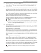
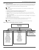
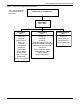
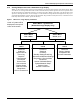
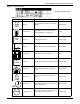
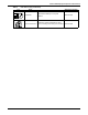
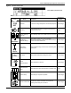
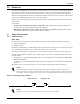
Table Of Contents
- 1.0 Introduction
- 2.0 Liebert iCOM Display Components and Functions
- Figure 2 Liebert iCOM display components
- Table 1 Keyboard icons and functions
- Figure 3 Status menu, large display, graphical view
- Figure 4 Liebert iCOM default screen symbols
- 2.1 Navigating Through the Liebert iCOM Menus
- 3.0 Operation
- 3.1 Single Unit Functions
- 3.2 Motorized Ball Valve in Digital Scroll Units
- 3.3 Temperature Control—Single Source Cooling (No Extra Cooling Coil)
- 3.3.1 Temperature Proportional Band
- 3.3.2 Compressor Control
- Compressor Proportional Bands
- Figure 12 One single-step compressor without unloaders
- Figure 13 Two single-step compressors without unloaders or one compressor with an unloader (two-step)
- Figure 14 Two compressors with unloaders (four-step)
- Figure 15 Digital scroll capacity modulation, 10-100% variable
- Figure 16 Single and dual digital scroll compressor activation points
- Compressor Proportional Bands
- 3.3.3 Chilled Water Control
- 3.4 Temperature Control—Second Cooling Source
- 3.5 Temperature Control—Reheat
- 3.6 Humidity Control
- 3.7 Control Types
- 3.8 Possible Event Notifications
- 3.9 Next Maintenance Calculation
- 4.0 Teamwork
- 5.0 Installing a Liebert iCOM Unit-to-Unit Network
- 5.1 Placement of Cooling Units
- 5.2 U2U Hardware: Cables and Network Switch
- 5.3 Wiring for Unit-to-Unit Communications—U2U
- 5.4 External Communications—Building Management Systems, Liebert SiteScan®
- 6.0 Mounting a Large Display on a Wall
- 7.0 User Menu Parameters
- 8.0 Service Menu Parameters
- Table 23 Setpoints parameters
- Unit Diary—Large Display Only
- Table 24 Unit diary parameters
- Table 25 Standby settings / lead-lag parameters
- Table 26 Maintenance / wellness settings parameters
- Table 27 Diagnostics / service mode parameters
- Table 28 Set alarms parameters
- Table 29 Sensor calibration / setup parameters
- Table 30 System / network setup parameters—large display only
- Table 31 Network setup parameters
- Table 32 Options setup parameters
- Table 33 Service contact info parameters
Liebert iCOM Display Components and Functions
6
2.1.3 Entering a Password
To change the value of a parameter in a menu, you must first enter the password for that menu. The
User, Service and Advanced menus each has a unique password to prevent unauthorized changes.
The User menu password is 1490; the Service menu password is 5010.
To enter a password:
1. Navigate to the menu that contains the parameter to be changed.
2. Select Password in the submenu by pressing the Enter key
3. Press the Enter key to move your cursor to the right side of the screen to select the question
marks.
4. Use the arrow keys to enter the numeral for the password’s first digit (the up arrow key moves
from 1 to the next digit).
5. Use the right arrow key to move to the next question mark and repeat Step 4 to enter all digits in
the password.
6. After entering the password, press enter.
If the password is correct, the Actual Level shown to the right of Password will change
from 0 to 1 or 2. The menu will remain locked if the password was incorrect.
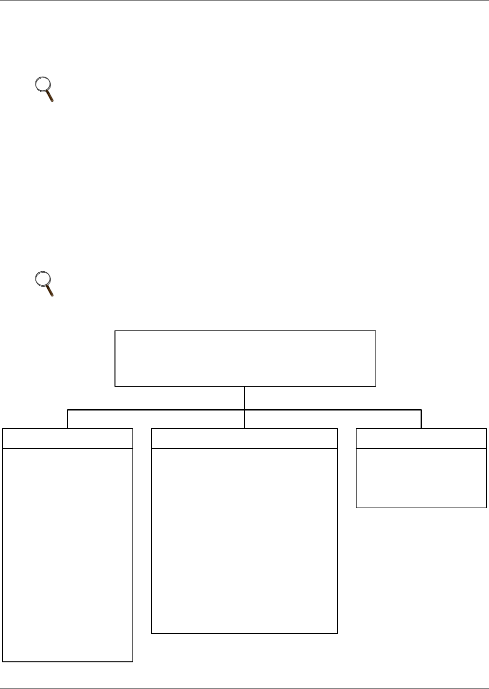
Figure 5 Menu tree—Small display, stand-alone or networked
NOTE
Entering the Service menu password permits access to both the User and Service menus.
NOTE
Returning to the Status menu will require re-entering a password to make changes.
Status Menu
Unit 1 View
User Menu
Password
Setpoints
Event Log
Graphics
Set Alarms
Sensor Data
Display Setup
Total Run Hours
Sleep Mode
Service Info
Active Alarms
Service Menu
Password
Setpoints
Standby
Wellness
Diagnostics
Set Alarms
Calibration
Network Setup
Options Setup
Service Info
Advanced Menu
Password
Factory Settings
Access Passwords