
Intelligent Communications & Monitoring System User Manual
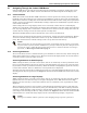
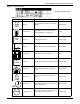
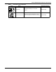
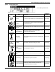
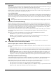
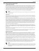
Table Of Contents
- 1.0 Introduction
- 2.0 Liebert iCOM Display Components and Functions
- Figure 2 Liebert iCOM display components
- Table 1 Keyboard icons and functions
- Figure 3 Status menu, large display, graphical view
- Figure 4 Liebert iCOM default screen symbols
- 2.1 Navigating Through the Liebert iCOM Menus
- 3.0 Operation
- 3.1 Single Unit Functions
- 3.2 Motorized Ball Valve in Digital Scroll Units
- 3.3 Temperature Control—Single Source Cooling (No Extra Cooling Coil)
- 3.3.1 Temperature Proportional Band
- 3.3.2 Compressor Control
- Compressor Proportional Bands
- Figure 12 One single-step compressor without unloaders
- Figure 13 Two single-step compressors without unloaders or one compressor with an unloader (two-step)
- Figure 14 Two compressors with unloaders (four-step)
- Figure 15 Digital scroll capacity modulation, 10-100% variable
- Figure 16 Single and dual digital scroll compressor activation points
- Compressor Proportional Bands
- 3.3.3 Chilled Water Control
- 3.4 Temperature Control—Second Cooling Source
- 3.5 Temperature Control—Reheat
- 3.6 Humidity Control
- 3.7 Control Types
- 3.8 Possible Event Notifications
- 3.9 Next Maintenance Calculation
- 4.0 Teamwork
- 5.0 Installing a Liebert iCOM Unit-to-Unit Network
- 5.1 Placement of Cooling Units
- 5.2 U2U Hardware: Cables and Network Switch
- 5.3 Wiring for Unit-to-Unit Communications—U2U
- 5.4 External Communications—Building Management Systems, Liebert SiteScan®
- 6.0 Mounting a Large Display on a Wall
- 7.0 User Menu Parameters
- 8.0 Service Menu Parameters
- Table 23 Setpoints parameters
- Unit Diary—Large Display Only
- Table 24 Unit diary parameters
- Table 25 Standby settings / lead-lag parameters
- Table 26 Maintenance / wellness settings parameters
- Table 27 Diagnostics / service mode parameters
- Table 28 Set alarms parameters
- Table 29 Sensor calibration / setup parameters
- Table 30 System / network setup parameters—large display only
- Table 31 Network setup parameters
- Table 32 Options setup parameters
- Table 33 Service contact info parameters
Liebert iCOM Display Components and Functions
11
Figure 9 Service menu icons
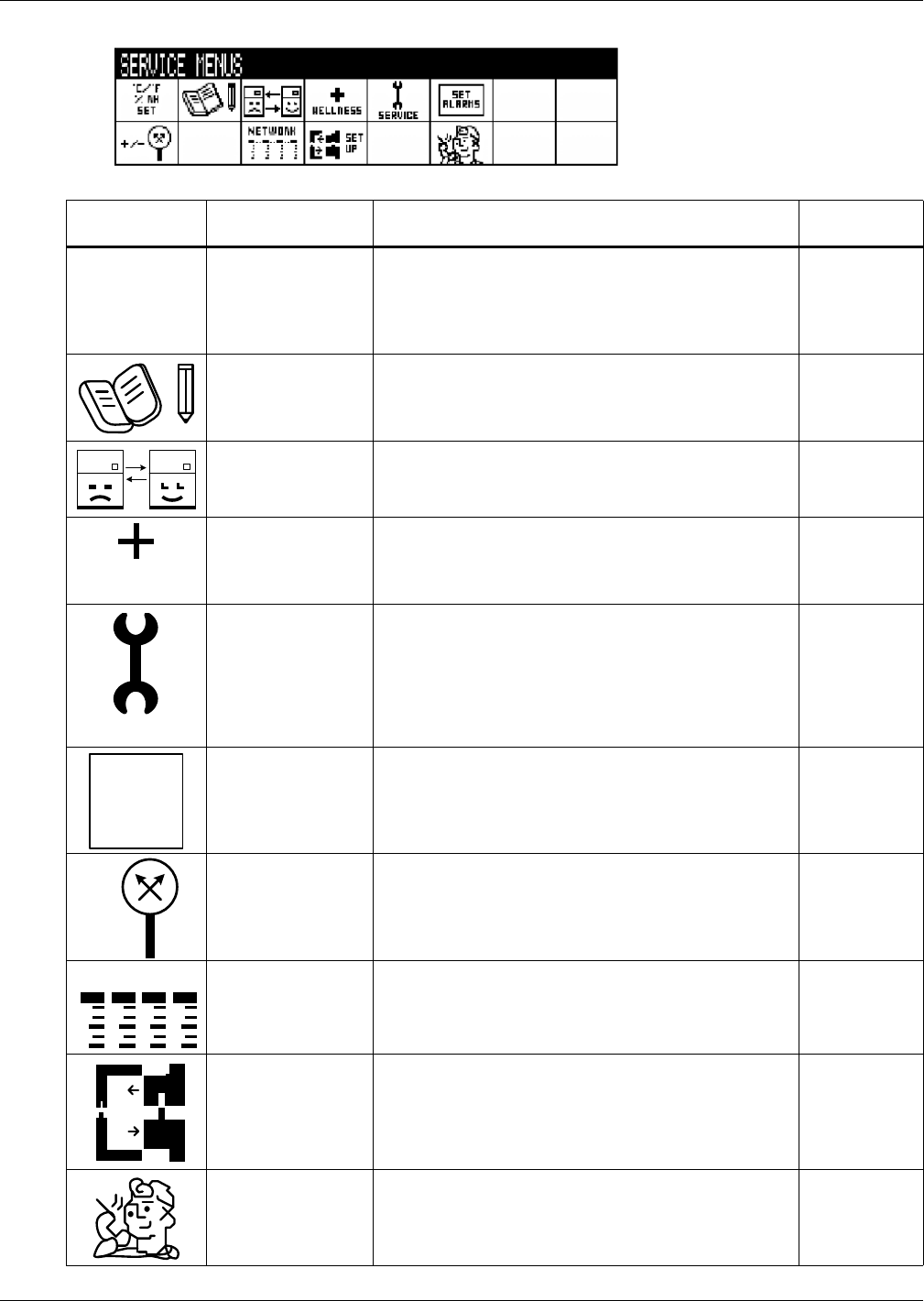
Table 3 Service menu icons
Icon Name
Description
Available On
Display
Setpoints To view and change temperature and humidity setpoints Small & large
Unit Diary
Shows all entered program changes and maintenance
performed on the unit
Large
Standby Settings/
Lead-Lag
Allows lead/lag setup when multiple units are connected Small & large
Maintenance/
Wellness Settings
Allows setting maintenance interval reminder,
maintenance message, number of unit starts and stops,
and time since last maintenance
Small & large
Diagnostics/
Service Mode
Allows troubleshooting, manual mode, read analog and
digital inputs
Small & large
Set Alarms Allows enable, disable and settings for alarms Small & large
Sensor
Calibration/Setup
Allows calibration of sensors Small & large
System/Network
Setup
Allows setup and U2U communication for multiple units Large
Options Setup Allows setup of component operation Small & large
Service Contact Info
Contains key contact information for local service,
including names and phone numbers
Small & large
Service Menu password: 5010
°C / °F
% RH
SET
WELLNESS
SERVICE
SET
ALARMS
+ / -
NETWORK