
Intelligent Communications & Monitoring System User Manual
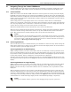
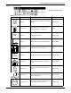
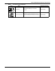
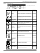
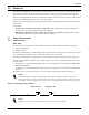
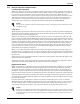
Table Of Contents
- 1.0 Introduction
- 2.0 Liebert iCOM Display Components and Functions
- Figure 2 Liebert iCOM display components
- Table 1 Keyboard icons and functions
- Figure 3 Status menu, large display, graphical view
- Figure 4 Liebert iCOM default screen symbols
- 2.1 Navigating Through the Liebert iCOM Menus
- 3.0 Operation
- 3.1 Single Unit Functions
- 3.2 Motorized Ball Valve in Digital Scroll Units
- 3.3 Temperature Control—Single Source Cooling (No Extra Cooling Coil)
- 3.3.1 Temperature Proportional Band
- 3.3.2 Compressor Control
- Compressor Proportional Bands
- Figure 12 One single-step compressor without unloaders
- Figure 13 Two single-step compressors without unloaders or one compressor with an unloader (two-step)
- Figure 14 Two compressors with unloaders (four-step)
- Figure 15 Digital scroll capacity modulation, 10-100% variable
- Figure 16 Single and dual digital scroll compressor activation points
- Compressor Proportional Bands
- 3.3.3 Chilled Water Control
- 3.4 Temperature Control—Second Cooling Source
- 3.5 Temperature Control—Reheat
- 3.6 Humidity Control
- 3.7 Control Types
- 3.8 Possible Event Notifications
- 3.9 Next Maintenance Calculation
- 4.0 Teamwork
- 5.0 Installing a Liebert iCOM Unit-to-Unit Network
- 5.1 Placement of Cooling Units
- 5.2 U2U Hardware: Cables and Network Switch
- 5.3 Wiring for Unit-to-Unit Communications—U2U
- 5.4 External Communications—Building Management Systems, Liebert SiteScan®
- 6.0 Mounting a Large Display on a Wall
- 7.0 User Menu Parameters
- 8.0 Service Menu Parameters
- Table 23 Setpoints parameters
- Unit Diary—Large Display Only
- Table 24 Unit diary parameters
- Table 25 Standby settings / lead-lag parameters
- Table 26 Maintenance / wellness settings parameters
- Table 27 Diagnostics / service mode parameters
- Table 28 Set alarms parameters
- Table 29 Sensor calibration / setup parameters
- Table 30 System / network setup parameters—large display only
- Table 31 Network setup parameters
- Table 32 Options setup parameters
- Table 33 Service contact info parameters
Operation
12
3.0 OPERATION
The Liebert iCOM display for your Liebert cooling unit features an easy-to-use, menu-driven liquid
crystal display (LCD). All unit settings and parameters can be viewed and adjusted through three
menus: User, Service and Advanced. All active alarms are displayed on the LCD and annunciated.
The control is shipped from the factory with default selections for all necessary settings. Adjustments
can be made if the defaults do not meet your requirements.
References to menu items in this manual are followed by the main menu and the submenu where they
can be found.
For example:
• Temperature Setpoint (User Menu, Setpoints) - The Temperature Setpoint parameter is
located in the User menu under the Setpoints submenu.
• High Return Humidity (Service Menu, Set Alarms) - The High Return Humidity alarm is
located in the Service menu under the Set Alarms submenu.
3.1 Single Unit Functions
3.1.1 Unit/Fan Control
Start - Stop
Unit on means the fan output is activated. The unit can be switched On and Off from two inputs:
1. Remote on/off input
2. Display button
Pressing the On/Off key on a small display will control only the cooling unit it is connected to regard-
less, of whether the cooling unit is a stand-alone unit or part of a network.
Pressing the On/Off key on a large display of a stand-alone cooling unit will control only that unit.
The effect of pressing the On/Off key on a large display connected to a network depends on the view:
System or Unit.
• In System view, pressing the On/Off key shows a warning asking for confirmation to shut down
the entire system.
• In Unit view, pressing the On/Off key affects only the unit being viewed, without a confirmation
request.
Each time a unit is powered on or off, an event is added to the Event Log in the User menu.
Figure 10 Start-stop priority switches
NOTE
Customer switches: remote On/Off (if used) and display On/Off switches are in series. A
cooling unit will start only if both switches are On; if one of these switches is Off, the unit will
stop. Safety devices within the unit are also in series and will shut the unit down if required.
NOTE
If Remote On/Off is not used, a jumper is inserted to bypass the switch.
Remote On / Off
Display On / Off