
Intelligent Communications & Monitoring System User Manual
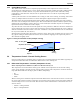
Table Of Contents
- 1.0 Introduction
- 2.0 Liebert iCOM Display Components and Functions
- Figure 2 Liebert iCOM display components
- Table 1 Keyboard icons and functions
- Figure 3 Status menu, large display, graphical view
- Figure 4 Liebert iCOM default screen symbols
- 2.1 Navigating Through the Liebert iCOM Menus
- 3.0 Operation
- 3.1 Single Unit Functions
- 3.2 Motorized Ball Valve in Digital Scroll Units
- 3.3 Temperature Control—Single Source Cooling (No Extra Cooling Coil)
- 3.3.1 Temperature Proportional Band
- 3.3.2 Compressor Control
- Compressor Proportional Bands
- Figure 12 One single-step compressor without unloaders
- Figure 13 Two single-step compressors without unloaders or one compressor with an unloader (two-step)
- Figure 14 Two compressors with unloaders (four-step)
- Figure 15 Digital scroll capacity modulation, 10-100% variable
- Figure 16 Single and dual digital scroll compressor activation points
- Compressor Proportional Bands
- 3.3.3 Chilled Water Control
- 3.4 Temperature Control—Second Cooling Source
- 3.5 Temperature Control—Reheat
- 3.6 Humidity Control
- 3.7 Control Types
- 3.8 Possible Event Notifications
- 3.9 Next Maintenance Calculation
- 4.0 Teamwork
- 5.0 Installing a Liebert iCOM Unit-to-Unit Network
- 5.1 Placement of Cooling Units
- 5.2 U2U Hardware: Cables and Network Switch
- 5.3 Wiring for Unit-to-Unit Communications—U2U
- 5.4 External Communications—Building Management Systems, Liebert SiteScan®
- 6.0 Mounting a Large Display on a Wall
- 7.0 User Menu Parameters
- 8.0 Service Menu Parameters
- Table 23 Setpoints parameters
- Unit Diary—Large Display Only
- Table 24 Unit diary parameters
- Table 25 Standby settings / lead-lag parameters
- Table 26 Maintenance / wellness settings parameters
- Table 27 Diagnostics / service mode parameters
- Table 28 Set alarms parameters
- Table 29 Sensor calibration / setup parameters
- Table 30 System / network setup parameters—large display only
- Table 31 Network setup parameters
- Table 32 Options setup parameters
- Table 33 Service contact info parameters

Operation
15
Digital Scroll High Temperature
A protective maximum operating compressor temperature limit is imposed on units with digital scroll
compressor(s) with thermistor. Once the digital scroll temperature reaches the maximum tempera-
ture threshold, the compressor will be locked out for at least 30 minutes and an alarm will be annun-
ciated. If after 30 minutes the temperature has cooled to a safe operating temperature, the
compressor will resume operation.
Each time a high-temperature alarm occurs, HT 1 Alarm Counter (Service Menu, Diagnostics) or
HT 2 Alarm Counter (Service Menu, Diagnostics) is increased by one. Once these counters reach five
occurrences in a rolling four-hour period, the compressor will be locked out. The alarm can be reset
once the temperature returns to a safe level by:
1. Setting the counter back to 0 from the display and pressing the alarm reset button.
2. Shutting off power to the control board by turning the cooling unit's main power disconnect switch
Off and On.
3.1.4 Compressor Timing—Units With Two Compressors
To help maximize the life of your compressor(s), there is a start-to-next start delay for each single
compressor.
A Minimum ON time and a Minimum Off time may be selected in the Advanced menu (minimum
three minutes for single phase compressors). Consult the factory on how to modify the Minimum ON
and OFF time settings.
3.1.5 Compressor Sequencing
Compressor Sequencing parameter (Service Menu, Options Setup) is intended to maintain equal run
times between compressors. This setting has three selection possibilities:
• Always use Compressor 1 as lead compressor
• Always use Compressor 2 as lead compressor
•Auto:
• First priority: if the safety timings are acceptable for only one compressor, then it is the next
to be started/stopped.
• If both compressors are off: the one with fewer working hours is the next to start.
• If both compressors are in operation: the one that has been operating longer since the last
start is the next to be stopped.
NOTE
The Auto setting attempts to maintain equal run times between compressors.