
Intelligent Communications & Monitoring System User Manual
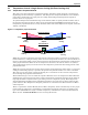
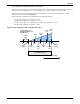
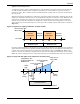
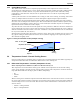
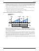
Table Of Contents
- 1.0 Introduction
- 2.0 Liebert iCOM Display Components and Functions
- Figure 2 Liebert iCOM display components
- Table 1 Keyboard icons and functions
- Figure 3 Status menu, large display, graphical view
- Figure 4 Liebert iCOM default screen symbols
- 2.1 Navigating Through the Liebert iCOM Menus
- 3.0 Operation
- 3.1 Single Unit Functions
- 3.2 Motorized Ball Valve in Digital Scroll Units
- 3.3 Temperature Control—Single Source Cooling (No Extra Cooling Coil)
- 3.3.1 Temperature Proportional Band
- 3.3.2 Compressor Control
- Compressor Proportional Bands
- Figure 12 One single-step compressor without unloaders
- Figure 13 Two single-step compressors without unloaders or one compressor with an unloader (two-step)
- Figure 14 Two compressors with unloaders (four-step)
- Figure 15 Digital scroll capacity modulation, 10-100% variable
- Figure 16 Single and dual digital scroll compressor activation points
- Compressor Proportional Bands
- 3.3.3 Chilled Water Control
- 3.4 Temperature Control—Second Cooling Source
- 3.5 Temperature Control—Reheat
- 3.6 Humidity Control
- 3.7 Control Types
- 3.8 Possible Event Notifications
- 3.9 Next Maintenance Calculation
- 4.0 Teamwork
- 5.0 Installing a Liebert iCOM Unit-to-Unit Network
- 5.1 Placement of Cooling Units
- 5.2 U2U Hardware: Cables and Network Switch
- 5.3 Wiring for Unit-to-Unit Communications—U2U
- 5.4 External Communications—Building Management Systems, Liebert SiteScan®
- 6.0 Mounting a Large Display on a Wall
- 7.0 User Menu Parameters
- 8.0 Service Menu Parameters
- Table 23 Setpoints parameters
- Unit Diary—Large Display Only
- Table 24 Unit diary parameters
- Table 25 Standby settings / lead-lag parameters
- Table 26 Maintenance / wellness settings parameters
- Table 27 Diagnostics / service mode parameters
- Table 28 Set alarms parameters
- Table 29 Sensor calibration / setup parameters
- Table 30 System / network setup parameters—large display only
- Table 31 Network setup parameters
- Table 32 Options setup parameters
- Table 33 Service contact info parameters

Operation
16
3.2 Motorized Ball Valve in Digital Scroll Units
On digital scroll units, discharge pressure is controlled by a motorized ball valve. During unloaded
operation, pressure changes during each digital cycle could cause a pressure-controlled water regulat-
ing valve to open and close an excessive number of times.
The motorized ball valve is designed to maintain a consistent peak discharge pressure on Water/Gly-
col Cooled Digital Compressor Systems.
The control algorithm for the motorized ball valve uses an intelligent sampling rate and adjustable
pressure thresholds to reduce the number of times the valve opens and closes. The valve assembly
consists of the brass valve, linkage and actuator.
Each compressor has one motorized ball valve that is driven by the analog output of the Liebert iCOM
control board based on pressure. If there is a call for cooling, the compressor start is delayed by a 30-
second timer. During this delay, the motorized ball valve is set to 50% open. The compressor will start
after the 30-second timer elapses.
Motorized Ball Valve Manual Mode: (Service/Service) Manual operation can be selected to allow
service personnel to control the motorized ball valve from the Liebert iCOM control only when the
system is in manual mode.
When Auto BV Control is selected, the motorized ball valve functions as it would be during normal
system operation.
When Manual BV Control is selected, the user must be careful in setting the analog output because
the ball valves will remain in the position set in the Service menu until the control is switched back to
Auto or until a technician changes the valves to another manual position (the motorized ball valve in
manual mode can be set in 1% increments from fully closed to fully open). Low- or high-discharge
pressure may occur during this mode, depending on environmental conditions and the position of the
motorized ball valve.
The motorized ball valve is driven by a 2-10VDC proportional control signal: the valve is closed at
2VDC, 50% open at 6VDC and fully open at 10 VDC.
3.2.1 MBV Operation After Compressor is Turned Off
Once a compressor has stopped, the MBV control will continue to change the MBV position to main-
tain system pressures for a maximum time of 10 minutes by following the auto control algorythm.
When the 10-minute delay has expired or the discharge pressure is below its minimum threshold the
motorized ball valve will close until the next compressor activation.
3.2.2 Service Offset—Changing System Pressure Settings
The MBV control is set to maintain a system pressure specific to the particular type of cooling unit. A
properly trained and qualified technician can increase or decrease the pressure through the Ball
Valve Setpoint Offset found in the Service/Options Setup menu. The range is 0 to 50 PSI; the default
is 30 PSI.
NOTE
Compressor operation will be delayed 30 seconds to allow the motorized ball valve to position
itself for initial startup.
NOTE
Adjusting this parameter will increase or decrease the operating compressor discharge
pressure by changing the targeted range of control. The discharge pressure is the peak pressure
of the digital cycle.