
Intelligent Communications & Monitoring System User Manual
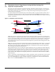
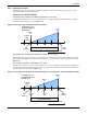
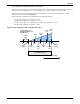
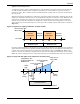
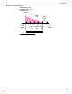
Table Of Contents
- 1.0 Introduction
- 2.0 Liebert iCOM Display Components and Functions
- Figure 2 Liebert iCOM display components
- Table 1 Keyboard icons and functions
- Figure 3 Status menu, large display, graphical view
- Figure 4 Liebert iCOM default screen symbols
- 2.1 Navigating Through the Liebert iCOM Menus
- 3.0 Operation
- 3.1 Single Unit Functions
- 3.2 Motorized Ball Valve in Digital Scroll Units
- 3.3 Temperature Control—Single Source Cooling (No Extra Cooling Coil)
- 3.3.1 Temperature Proportional Band
- 3.3.2 Compressor Control
- Compressor Proportional Bands
- Figure 12 One single-step compressor without unloaders
- Figure 13 Two single-step compressors without unloaders or one compressor with an unloader (two-step)
- Figure 14 Two compressors with unloaders (four-step)
- Figure 15 Digital scroll capacity modulation, 10-100% variable
- Figure 16 Single and dual digital scroll compressor activation points
- Compressor Proportional Bands
- 3.3.3 Chilled Water Control
- 3.4 Temperature Control—Second Cooling Source
- 3.5 Temperature Control—Reheat
- 3.6 Humidity Control
- 3.7 Control Types
- 3.8 Possible Event Notifications
- 3.9 Next Maintenance Calculation
- 4.0 Teamwork
- 5.0 Installing a Liebert iCOM Unit-to-Unit Network
- 5.1 Placement of Cooling Units
- 5.2 U2U Hardware: Cables and Network Switch
- 5.3 Wiring for Unit-to-Unit Communications—U2U
- 5.4 External Communications—Building Management Systems, Liebert SiteScan®
- 6.0 Mounting a Large Display on a Wall
- 7.0 User Menu Parameters
- 8.0 Service Menu Parameters
- Table 23 Setpoints parameters
- Unit Diary—Large Display Only
- Table 24 Unit diary parameters
- Table 25 Standby settings / lead-lag parameters
- Table 26 Maintenance / wellness settings parameters
- Table 27 Diagnostics / service mode parameters
- Table 28 Set alarms parameters
- Table 29 Sensor calibration / setup parameters
- Table 30 System / network setup parameters—large display only
- Table 31 Network setup parameters
- Table 32 Options setup parameters
- Table 33 Service contact info parameters
Operation
17
3.3 Temperature Control—Single Source Cooling (No Extra Cooling Coil)
3.3.1 Temperature Proportional Band
The control uses the temperature proportional band to determine which operation to perform (cool-
ing/heating) and how intensely to perform it. The Temperature Proportional Band is a user-defined
range that is divided into two equal parts for cooling and heating. The Temperature Setpoint is
between these two equal parts.
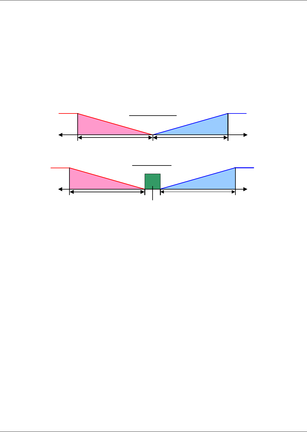
An optional Temperature Deadband range can be defined, which is equally divided on either side of
the setpoint and separates the two halves of the proportional band. Figure 11 illustrates how the
temperature proportional band is evenly divided on either side of the temperature setpoint, with and
without a deadband.
Figure 11 Temperature proportional band
When the return air temperature deviates from the setpoint it begins to penetrate one of the propor-
tional band halves, cooling or heating. If the return air temperature increases, the control calls for 0%
(none) to 100% (full) cooling capacity based on how far the temperature penetrates the cooling portion
of the proportional band. If the return air temperature decreases, the control calls for 0% (none) to -
100% (full) heating capacity based on how far the temperature penetrates the heating portion of the
proportional band.
When the return air temperature reaches the end of the proportional band, either 100% or -100%, full
cooling or full heating capacity is provided. No operation is performed when a 0% call is calculated.
The control varies the call for cooling and heating in 1% increments as the return air temperature
moves through the proportional band halves.
The deadband range is used to widen the setpoint. When the return air temperature falls within the
deadband, the control operates the same as if the temperature equaled the setpoint exactly. This set-
ting helps maximize component life by preventing excessive component cycling. The Temperature
Proportional Band and Temperature Deadband parameters are in the Service menu under the Set-
points submenu. The Temperature Setpoint parameter is in both the User Menu and Service Menu
under Setpoints.
There is a parameter AutoSet Enable (Service Menu, Setpoints), which automatically sets the propor-
tional bands for temperature and humidity, and both the integration time factors according to the
type of unit (Chilled Water, single or double compressor), with influence of the selected Teamwork
Mode. See 4.1 - Teamwork Modes for more on using this feature.
0%
Setpoint
0%
Cooling
+ Temp
+ 100%
Cooling
½ Proportional Band
Dead -
band
-Temp
Heating
-100%
Heating
½ Proportional Band
CoolingHeating
-Temp + Temp
0%
Setpoint
+ 100%
Cooling
-100%
Heating
½ Proportional Band½ Proportional Band
With Deadband
Without Deadband