
Intelligent Communications & Monitoring System User Manual
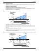
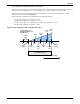
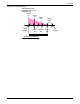
Table Of Contents
- 1.0 Introduction
- 2.0 Liebert iCOM Display Components and Functions
- Figure 2 Liebert iCOM display components
- Table 1 Keyboard icons and functions
- Figure 3 Status menu, large display, graphical view
- Figure 4 Liebert iCOM default screen symbols
- 2.1 Navigating Through the Liebert iCOM Menus
- 3.0 Operation
- 3.1 Single Unit Functions
- 3.2 Motorized Ball Valve in Digital Scroll Units
- 3.3 Temperature Control—Single Source Cooling (No Extra Cooling Coil)
- 3.3.1 Temperature Proportional Band
- 3.3.2 Compressor Control
- Compressor Proportional Bands
- Figure 12 One single-step compressor without unloaders
- Figure 13 Two single-step compressors without unloaders or one compressor with an unloader (two-step)
- Figure 14 Two compressors with unloaders (four-step)
- Figure 15 Digital scroll capacity modulation, 10-100% variable
- Figure 16 Single and dual digital scroll compressor activation points
- Compressor Proportional Bands
- 3.3.3 Chilled Water Control
- 3.4 Temperature Control—Second Cooling Source
- 3.5 Temperature Control—Reheat
- 3.6 Humidity Control
- 3.7 Control Types
- 3.8 Possible Event Notifications
- 3.9 Next Maintenance Calculation
- 4.0 Teamwork
- 5.0 Installing a Liebert iCOM Unit-to-Unit Network
- 5.1 Placement of Cooling Units
- 5.2 U2U Hardware: Cables and Network Switch
- 5.3 Wiring for Unit-to-Unit Communications—U2U
- 5.4 External Communications—Building Management Systems, Liebert SiteScan®
- 6.0 Mounting a Large Display on a Wall
- 7.0 User Menu Parameters
- 8.0 Service Menu Parameters
- Table 23 Setpoints parameters
- Unit Diary—Large Display Only
- Table 24 Unit diary parameters
- Table 25 Standby settings / lead-lag parameters
- Table 26 Maintenance / wellness settings parameters
- Table 27 Diagnostics / service mode parameters
- Table 28 Set alarms parameters
- Table 29 Sensor calibration / setup parameters
- Table 30 System / network setup parameters—large display only
- Table 31 Network setup parameters
- Table 32 Options setup parameters
- Table 33 Service contact info parameters
Operation
19
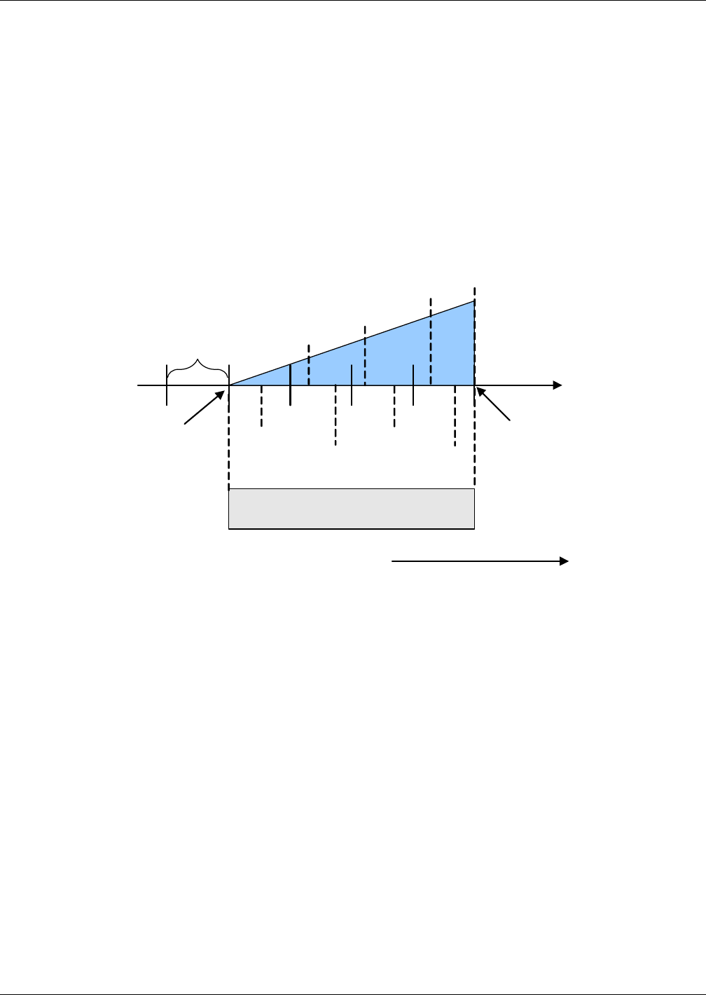
Two Compressors With Unloaders—Four-Step
The first two-step compressor is started unloaded at 33% calculated output from the temperature pro-
portional band and stopped at 17%. At 80% Compressor 1 will be loaded, at 70% unloaded.
The second compressor starts unloaded at 63% and stops at 47%. At 100%, Compressor 2 will be
loaded, at 90% unloaded (see Figure 14).
The four stages of cooling are accomplished in the following manner:
• 1 stage: One compressor, unloaded - Cool 1
• 2 stages: Both compressors, unloaded - Cool 2
• 3 stages: One compressor, loaded and one compressor, unloaded - Cool 3
• 4 stages: Both compressors, loaded - Cool 4
Figure 14 Two compressors with unloaders (four-step)
Cool 2
On
Temp Setpoint : 70°F
Proportional Band: 8°F
Deadband : 2°F
½ Dead-
band
Increasing Temperature
½ Proportional Band
757473727170
0%
Cooling
+ 100%
Cooling
Cool 4
Off
Cool 2
Off
Cool 1
Off
Cool 4
On
Cool 3
On
Cool 1
On
Cool 3
Off