
Intelligent Communications & Monitoring System User Manual
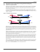
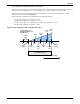
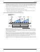
Table Of Contents
- 1.0 Introduction
- 2.0 Liebert iCOM Display Components and Functions
- Figure 2 Liebert iCOM display components
- Table 1 Keyboard icons and functions
- Figure 3 Status menu, large display, graphical view
- Figure 4 Liebert iCOM default screen symbols
- 2.1 Navigating Through the Liebert iCOM Menus
- 3.0 Operation
- 3.1 Single Unit Functions
- 3.2 Motorized Ball Valve in Digital Scroll Units
- 3.3 Temperature Control—Single Source Cooling (No Extra Cooling Coil)
- 3.3.1 Temperature Proportional Band
- 3.3.2 Compressor Control
- Compressor Proportional Bands
- Figure 12 One single-step compressor without unloaders
- Figure 13 Two single-step compressors without unloaders or one compressor with an unloader (two-step)
- Figure 14 Two compressors with unloaders (four-step)
- Figure 15 Digital scroll capacity modulation, 10-100% variable
- Figure 16 Single and dual digital scroll compressor activation points
- Compressor Proportional Bands
- 3.3.3 Chilled Water Control
- 3.4 Temperature Control—Second Cooling Source
- 3.5 Temperature Control—Reheat
- 3.6 Humidity Control
- 3.7 Control Types
- 3.8 Possible Event Notifications
- 3.9 Next Maintenance Calculation
- 4.0 Teamwork
- 5.0 Installing a Liebert iCOM Unit-to-Unit Network
- 5.1 Placement of Cooling Units
- 5.2 U2U Hardware: Cables and Network Switch
- 5.3 Wiring for Unit-to-Unit Communications—U2U
- 5.4 External Communications—Building Management Systems, Liebert SiteScan®
- 6.0 Mounting a Large Display on a Wall
- 7.0 User Menu Parameters
- 8.0 Service Menu Parameters
- Table 23 Setpoints parameters
- Unit Diary—Large Display Only
- Table 24 Unit diary parameters
- Table 25 Standby settings / lead-lag parameters
- Table 26 Maintenance / wellness settings parameters
- Table 27 Diagnostics / service mode parameters
- Table 28 Set alarms parameters
- Table 29 Sensor calibration / setup parameters
- Table 30 System / network setup parameters—large display only
- Table 31 Network setup parameters
- Table 32 Options setup parameters
- Table 33 Service contact info parameters
Operation
22
The Value setting is the factory default setting on free-cooling and dual cooling units. If the tempera-
ture difference between the second source cooling fluid parameter, Free-cooling Fluid Temperature
(User Menu, Sensor Data) and room air is equal to or greater than the adjustable DT Between Room
Air / FC Fluid (Service Menu, Setpoints) value, then the second source cooling fluid will be used to
provide at least partial cooling (delta T between room and glycol = true).
Sensors used for this delta T are: room/local sensor or the return air sensor; and the glycol sensor.
If this delta T is true, the following actions will be performed:
1. The Free-Cooling Status indication will show “On” instead of “Off”.
2. The compressor band will be shifted to the right by 100%, and within the first 100% the free-
cooling valve band will take place (see Figure 18).
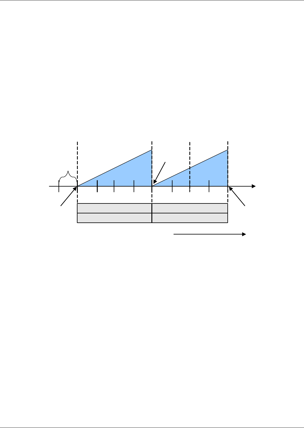
Figure 18 Second cooling source and compressorized cooling
Minimum Chilled Water Temperature—This feature permits the user to select the minimum
chilled water temperature that allows simultaneous operation of the second cooling source (chilled
water control) and compressor control. This feature is enabled in the Service menu under Setpoints,
parameter Minimum CW Temp.
Below this minimum chilled water setpoint, parameter Minimum CW Temp Value, (Service Menu,
Setpoints), the control will operate ONLY the second cooling source control, i.e., the compressor is
locked out. Above the minimum chilled water setpoint, assuming the fluid temperature is below the
return room air temperature (delta T between room and glycol = true), the control will operate the
second cooling source control and compressor control simultaneously if needed.
If the Minimum CW Temp is disabled, the second cooling source temperature is ignored, the control
will always operate the second cooling source and compressors simultaneously when the load requires
it.
7571 72 73 7470
Increasing Temperature
Cool 2
On
Cool 1
On
+ 100%
Cooling
Valve 100%
Open
Valve
Closed
½ Dead -
band
76 77 78 79
+ 200%
Cooling
0%
Cooling
2nd
Source
Comp
½ Proportional Band ½ Proportional Band
Band1: 2
nd
Source Band 2: Compressors
Temp Setpoint: 70°F
Proportional Band: 8°F
Deadband: 2°F