
Intelligent Communications & Monitoring System User Manual
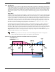
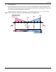
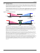
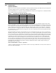
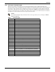
Table Of Contents
- 1.0 Introduction
- 2.0 Liebert iCOM Display Components and Functions
- Figure 2 Liebert iCOM display components
- Table 1 Keyboard icons and functions
- Figure 3 Status menu, large display, graphical view
- Figure 4 Liebert iCOM default screen symbols
- 2.1 Navigating Through the Liebert iCOM Menus
- 3.0 Operation
- 3.1 Single Unit Functions
- 3.2 Motorized Ball Valve in Digital Scroll Units
- 3.3 Temperature Control—Single Source Cooling (No Extra Cooling Coil)
- 3.3.1 Temperature Proportional Band
- 3.3.2 Compressor Control
- Compressor Proportional Bands
- Figure 12 One single-step compressor without unloaders
- Figure 13 Two single-step compressors without unloaders or one compressor with an unloader (two-step)
- Figure 14 Two compressors with unloaders (four-step)
- Figure 15 Digital scroll capacity modulation, 10-100% variable
- Figure 16 Single and dual digital scroll compressor activation points
- Compressor Proportional Bands
- 3.3.3 Chilled Water Control
- 3.4 Temperature Control—Second Cooling Source
- 3.5 Temperature Control—Reheat
- 3.6 Humidity Control
- 3.7 Control Types
- 3.8 Possible Event Notifications
- 3.9 Next Maintenance Calculation
- 4.0 Teamwork
- 5.0 Installing a Liebert iCOM Unit-to-Unit Network
- 5.1 Placement of Cooling Units
- 5.2 U2U Hardware: Cables and Network Switch
- 5.3 Wiring for Unit-to-Unit Communications—U2U
- 5.4 External Communications—Building Management Systems, Liebert SiteScan®
- 6.0 Mounting a Large Display on a Wall
- 7.0 User Menu Parameters
- 8.0 Service Menu Parameters
- Table 23 Setpoints parameters
- Unit Diary—Large Display Only
- Table 24 Unit diary parameters
- Table 25 Standby settings / lead-lag parameters
- Table 26 Maintenance / wellness settings parameters
- Table 27 Diagnostics / service mode parameters
- Table 28 Set alarms parameters
- Table 29 Sensor calibration / setup parameters
- Table 30 System / network setup parameters—large display only
- Table 31 Network setup parameters
- Table 32 Options setup parameters
- Table 33 Service contact info parameters

Operation
28
3.6.1 Humidification
Infrared Humidifier
There are two types of infrared humidifiers: small pan (IFS) and large pan (IFL). The operating mode
of each is similar, however, some of the variables or timings differ.
Infrared humidifiers are started at 100% humidification request, and stopped at 0%. Infrared humid-
ifiers cannot be driven in proportional mode.
An autoflush system automatically controls a water makeup valve to maintain proper levels in the
infrared humidifier water pan during humidifier operation. If humidification is needed and 15 hours
have elapsed since the last time the humidifier was on, then the humidifier is not turned on until the
valve completes an initial fill of the humidifier pan. This pre-fill is about 30 seconds for a small pan
and 60 seconds for a large pan. The valve continues to fill and flush the pan for about 4-1/2 minutes
for a small pan or 7-1/2 minutes for a large pan. Pan size is selected based on unit specifications and
is preset at the factory.
During humidifier operation, with the flush rate set at the default of 150%, the valve is opened peri-
odically to add water to the pan (about 45 seconds every 7 minutes of humidifier operation for a small
pan, or 80 seconds every 10 minutes of operation for a large pan). This adds enough water to the pan
to cause about a third of the total water used to be flushed out of the overflow standpipe located in the
humidifier pan. This action helps to remove solids from the pan. The flush rate is adjustable from
110% to 500% in 10% intervals. Default is 150%. If the water quality is poor, it may be desirable to
increase the water flushing action above the normal 150% rate. Also, if the supply water pressure is
low, the flush rate adjustment can be increased so that sufficient water level is maintained during
humidification. The flush rate parameter, Infrared Flush Rate (Service Menu, Options Setup), is
adjustable from 110%-500%.
External Humidifier Control—Optional
A factory-supplied option may be provided to allow a start-stop command to be sent to the control of a
remote-mounted humidifier.
Table 5 Parameters for infrared humidifier control
Parameter IFS Default IFL Default
Humidity in Last xx Hours 15 hours 15 hours
Prefill Time 30 seconds 60 seconds
Fill Time 4 minutes 7 minutes
Humidifier On Time 8 or 10 minutes 10 minutes
Flush Rate 150% 150%