
Intelligent Communications & Monitoring System User Manual
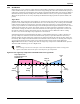
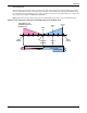
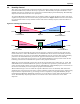
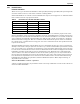
Table Of Contents
- 1.0 Introduction
- 2.0 Liebert iCOM Display Components and Functions
- Figure 2 Liebert iCOM display components
- Table 1 Keyboard icons and functions
- Figure 3 Status menu, large display, graphical view
- Figure 4 Liebert iCOM default screen symbols
- 2.1 Navigating Through the Liebert iCOM Menus
- 3.0 Operation
- 3.1 Single Unit Functions
- 3.2 Motorized Ball Valve in Digital Scroll Units
- 3.3 Temperature Control—Single Source Cooling (No Extra Cooling Coil)
- 3.3.1 Temperature Proportional Band
- 3.3.2 Compressor Control
- Compressor Proportional Bands
- Figure 12 One single-step compressor without unloaders
- Figure 13 Two single-step compressors without unloaders or one compressor with an unloader (two-step)
- Figure 14 Two compressors with unloaders (four-step)
- Figure 15 Digital scroll capacity modulation, 10-100% variable
- Figure 16 Single and dual digital scroll compressor activation points
- Compressor Proportional Bands
- 3.3.3 Chilled Water Control
- 3.4 Temperature Control—Second Cooling Source
- 3.5 Temperature Control—Reheat
- 3.6 Humidity Control
- 3.7 Control Types
- 3.8 Possible Event Notifications
- 3.9 Next Maintenance Calculation
- 4.0 Teamwork
- 5.0 Installing a Liebert iCOM Unit-to-Unit Network
- 5.1 Placement of Cooling Units
- 5.2 U2U Hardware: Cables and Network Switch
- 5.3 Wiring for Unit-to-Unit Communications—U2U
- 5.4 External Communications—Building Management Systems, Liebert SiteScan®
- 6.0 Mounting a Large Display on a Wall
- 7.0 User Menu Parameters
- 8.0 Service Menu Parameters
- Table 23 Setpoints parameters
- Unit Diary—Large Display Only
- Table 24 Unit diary parameters
- Table 25 Standby settings / lead-lag parameters
- Table 26 Maintenance / wellness settings parameters
- Table 27 Diagnostics / service mode parameters
- Table 28 Set alarms parameters
- Table 29 Sensor calibration / setup parameters
- Table 30 System / network setup parameters—large display only
- Table 31 Network setup parameters
- Table 32 Options setup parameters
- Table 33 Service contact info parameters
Operation
29
3.6.2 Dehumidification
The Dehumidification Enable parameter (Service Menu, Options Setup) allows for enabling/disabling
the dehumidification function.
A call for dehumidification is calculated in the same way as a cooling request. The components
(valves, compressors) will follow this dehumidification request as soon as it is higher than the request
for cooling.
Dehumidification Low Limit
Low Limit 1 and Low Limit 2 are used to avoid overcooling a room during dehumidification. When a
low limit is reached, a compressor or the liquid cooling source that is used for dehumidification is dis-
abled. It is re-enabled when the return air temperature rises. The Low Limit 1 and 2 settings are in
the Service menu under Setpoints.
Low Limit 1: Low Limit 1 will disable one of two compressors for dehumidification. If only one com-
pressor is set for dehumidification, or if the dehumidification source is chilled water, this limit will
not be visible and will be inactive.
Low Limit 2: Low Limit 2 will disable both compressors for dehumidification. This limit will also
stop dehumidification in single compressor units and in chilled water units.
The limits become active when the return air temperature drops below a temperature value equal to
the sum of the temperature setpoint plus the value set on Low Limit 1 and 2 (the Low Limit settings
are negative values).
A dehumidification source is deactivated if the return air temperature drops below the Deactivation
Temperature, as in this example:
Dehumidification Compressor Quantity
Under Factory Settings in the Advanced menu there is an item called Dehumidification With Comp.
This item will be set to either 1, 2, 1 or 2, or BOTH. This setting determines which compressors are
used for dehumidification. It also determines if Low Limit 1 will be available and impacts how the
reheats will operate during dehumidification. The Dehumidification With Comp field is set when the
cooling unit is built and should not be adjusted without consulting the factory first. Table 6 outlines
which Low Limit settings will be available, based on the Dehumidification With Comp selection.
Low Limit 1 & 2 will be available only on cooling units with two compressors when Dehumidification
With Comp is set to BOTH (see WARNING on page 30).
Temperature Setpoint: 70°F
Low Limit Value: -7°F
Deactivation Temperature: 62°F
NOTE
If a cooling unit is equipped with SCR reheat and the SCR Control Type parameter is set to
Tight mode, then Low Limit 2 will be ignored, see 3.5 - Temperature Control—Reheat.
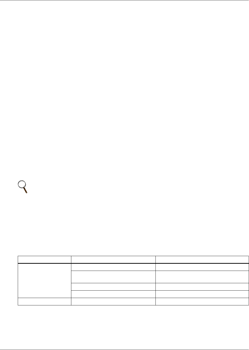
Table 6 Dehumidification With Comp settings
Available to Set Value Dehumidification With Comp Setting Default Setting On
Low Limit 2 only
[blank] (units without compressors) All Chilled Water Units
1 (Compressor 1 dehumidifies only) Liebert Challenger 3000
™
, Liebert DS
™
,
Liebert Deluxe System/3
™
2 (Compressor 2 dehumidifies only) —
1 or 2 (Compressor 1 and 2 alternate) —
Low Limit 1 & 2 Both (both compressors dehumidify) —