
Intelligent Communications & Monitoring System User Manual
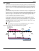
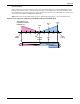
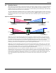
Table Of Contents
- 1.0 Introduction
- 2.0 Liebert iCOM Display Components and Functions
- Figure 2 Liebert iCOM display components
- Table 1 Keyboard icons and functions
- Figure 3 Status menu, large display, graphical view
- Figure 4 Liebert iCOM default screen symbols
- 2.1 Navigating Through the Liebert iCOM Menus
- 3.0 Operation
- 3.1 Single Unit Functions
- 3.2 Motorized Ball Valve in Digital Scroll Units
- 3.3 Temperature Control—Single Source Cooling (No Extra Cooling Coil)
- 3.3.1 Temperature Proportional Band
- 3.3.2 Compressor Control
- Compressor Proportional Bands
- Figure 12 One single-step compressor without unloaders
- Figure 13 Two single-step compressors without unloaders or one compressor with an unloader (two-step)
- Figure 14 Two compressors with unloaders (four-step)
- Figure 15 Digital scroll capacity modulation, 10-100% variable
- Figure 16 Single and dual digital scroll compressor activation points
- Compressor Proportional Bands
- 3.3.3 Chilled Water Control
- 3.4 Temperature Control—Second Cooling Source
- 3.5 Temperature Control—Reheat
- 3.6 Humidity Control
- 3.7 Control Types
- 3.8 Possible Event Notifications
- 3.9 Next Maintenance Calculation
- 4.0 Teamwork
- 5.0 Installing a Liebert iCOM Unit-to-Unit Network
- 5.1 Placement of Cooling Units
- 5.2 U2U Hardware: Cables and Network Switch
- 5.3 Wiring for Unit-to-Unit Communications—U2U
- 5.4 External Communications—Building Management Systems, Liebert SiteScan®
- 6.0 Mounting a Large Display on a Wall
- 7.0 User Menu Parameters
- 8.0 Service Menu Parameters
- Table 23 Setpoints parameters
- Unit Diary—Large Display Only
- Table 24 Unit diary parameters
- Table 25 Standby settings / lead-lag parameters
- Table 26 Maintenance / wellness settings parameters
- Table 27 Diagnostics / service mode parameters
- Table 28 Set alarms parameters
- Table 29 Sensor calibration / setup parameters
- Table 30 System / network setup parameters—large display only
- Table 31 Network setup parameters
- Table 32 Options setup parameters
- Table 33 Service contact info parameters

Operation
31
Intelligent – If Intelligent Control is selected, the return air temperature/humidity is controlled at or
near the setpoint. The percent temperature/humidity adjustment required is calculated based on logic
that is programmed into the control. These rules simulate the actions that a human operator would
take if manually controlling the system. This control type is commonly selected on chilled water units.
3.7.2 Humidity Sensor Reading Control Types
The Liebert iCOM control has three humidity sensor control types: Relative, Compensated and Pre-
dictive. The humidity sensor control adjusts how the Temperature and Humidity Control determines
the percent requirement for humidification/dehumidification. The humidity sensor control type
parameter, Humidity Control Type, is in both the User and Service menus under Setpoints.
Relative—The actual return air humidity sensor reading is sent to the Temperature and Humidity
Control to determine if and how much humidification/dehumidification is required. The actual return
air humidity reading is displayed on the Status menu. Unnecessary dehumidification can result when
overcooling occurs during a dehumidification cycle. This is because a higher than normal relative
humidity (RH) reading is caused by overcooling the room. This extends the dehumidification cycle.
Later, when the dehumidification ends and the return air temperature rises to the setpoint, the RH
reading falls. The final RH reading will then be lower than actually desired. If significant overcooling
occurred, the RH could be low enough to activate the humidifier.
Compensated—The actual return air humidity sensor reading is sent to the Temperature and
Humidity Control where the Humidity Setpoint is adjusted based on how much the return room air
temperature deviates from the desired temperature setpoint. The adjusted humidity setpoint is used
for humidification percent requirement determination. For every 1°C deviation from the temperature
setpoint the humidity setpoint is changed by 3% RH, inversely proportional: if the temperature
increases, the humidity setpoint is decreased, and vice versa. The recalculated humidity setpoint is
shown as the Actual Humidity Setpoint (User Menu, Sensor Data). As the humidity setpoint is auto-
matically adjusted, the high and low humidity setpoints (User Menu, Set Alarms) are adjusted
accordingly. The unadjusted humidity sensor reading is displayed on the Status menu.
Predictive—The actual return air humidity sensor reading is adjusted before it is sent to the Tem-
perature and Humidity Control. The humidity sensor reading is adjusted based on how much the
return room air temperature deviates from the desired temperature setpoint. For every 1°C deviation
from the temperature setpoint, the humidity sensor reading is changed by 3% RH, directly propor-
tional: if the temperature increases, the humidity reading is increased and vice versa. The adjusted
humidity sensor reading is displayed on the Status menu. Units are shipped from the factory with
Predictive humidity control set as default.
If Compensated or Predictive humidity sensor control is selected, overdehumidification is avoided.
When overcooling occurs, causing an increase in the relative humidity sensor reading, the humidity
control program predicts what the RH will be when the dehumidification cycle ends and return air
temperature returns to the setpoint. This allows the dehumidification cycle to end at the proper time.
The Compensated and Predictive humidity sensor control can reduce energy consumption by mini-
mizing compressor and reheat operation, and eliminating unnecessary humidifier operation.
NOTE
The actual return air temperature sensor reading is always displayed on the Status menu. The
value displayed for the return air humidity sensor reading depends on the Humidity Sensor
Control Type (see 3.7.2 - Humidity Sensor Reading Control Types).
NOTE
The historical humidity sensor graphs will display the real (unadjusted) sensor readings, no
matter which Humidity Control Sensor Type is selected. The graphical sensor data is in the
User menu under Graphics.