
Intelligent Communications & Monitoring System User Manual
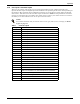
Table Of Contents
- 1.0 Introduction
- 2.0 Liebert iCOM Display Components and Functions
- Figure 2 Liebert iCOM display components
- Table 1 Keyboard icons and functions
- Figure 3 Status menu, large display, graphical view
- Figure 4 Liebert iCOM default screen symbols
- 2.1 Navigating Through the Liebert iCOM Menus
- 3.0 Operation
- 3.1 Single Unit Functions
- 3.2 Motorized Ball Valve in Digital Scroll Units
- 3.3 Temperature Control—Single Source Cooling (No Extra Cooling Coil)
- 3.3.1 Temperature Proportional Band
- 3.3.2 Compressor Control
- Compressor Proportional Bands
- Figure 12 One single-step compressor without unloaders
- Figure 13 Two single-step compressors without unloaders or one compressor with an unloader (two-step)
- Figure 14 Two compressors with unloaders (four-step)
- Figure 15 Digital scroll capacity modulation, 10-100% variable
- Figure 16 Single and dual digital scroll compressor activation points
- Compressor Proportional Bands
- 3.3.3 Chilled Water Control
- 3.4 Temperature Control—Second Cooling Source
- 3.5 Temperature Control—Reheat
- 3.6 Humidity Control
- 3.7 Control Types
- 3.8 Possible Event Notifications
- 3.9 Next Maintenance Calculation
- 4.0 Teamwork
- 5.0 Installing a Liebert iCOM Unit-to-Unit Network
- 5.1 Placement of Cooling Units
- 5.2 U2U Hardware: Cables and Network Switch
- 5.3 Wiring for Unit-to-Unit Communications—U2U
- 5.4 External Communications—Building Management Systems, Liebert SiteScan®
- 6.0 Mounting a Large Display on a Wall
- 7.0 User Menu Parameters
- 8.0 Service Menu Parameters
- Table 23 Setpoints parameters
- Unit Diary—Large Display Only
- Table 24 Unit diary parameters
- Table 25 Standby settings / lead-lag parameters
- Table 26 Maintenance / wellness settings parameters
- Table 27 Diagnostics / service mode parameters
- Table 28 Set alarms parameters
- Table 29 Sensor calibration / setup parameters
- Table 30 System / network setup parameters—large display only
- Table 31 Network setup parameters
- Table 32 Options setup parameters
- Table 33 Service contact info parameters

Operation
34
3.7.6 Event Types and Properties
Liebert iCOM events are used to inform the user of cooling unit operational status. All events are
recorded in the Event Log, which is in the User Menu. The user can change the type (alarm, warn,
message) and time delay of some events and can also enable or disable some events. These event set-
tings are in the Service Menu under Set Alarms, pages 3 to 7. If an event has a safety function (high
pressure, low pressure, main fan overload, etc.) the safety function will be executed in any case, inde-
pendent of the selected event type or if enabled or disabled. The timing will function as set.
Event Types
• Message: If this event occurs, it will only be entered into the event log.
• Warning: If this event occurs, a warning will be generated and entered into the event log. The
general alarm relay will be activated only if parameter Warning Activates Alarm Relay located in
the Service menu under Alarm Setup is set to Yes (Yes is the default setting from the factory)
• Alarm: If this event occurs, an alarm will be generated and entered into the event log. An alarm
does not necessarily switch off the whole cooling unit; it depends on which alarm occurs. If a
standby unit is set, any alarm will stop the faulty unit and ask the standby unit to start. Standby
activation is achieved on alarms ONLY; messages or warnings will not start the standby unit. For
more on standby units, see 4.0 - Teamwork.
Time Delay
Delays the event reaction once it is triggered. The time delay applies to safety functions and is
entered in seconds.
Enable or Disable
Disabled events do not show up in the event log, on the display or on monitoring devices. Also, the
common alarm relay will not be activated if a disabled alarm occurs. Safety functions, such as lockout
compressor in case of high pressure are still performed.
NOTE
Not all critical event properties can be adjusted.
NOTE
Once a disabled event (set to Warn or to Alarm) becomes active, it will lock itself. Disabled
events may be reset only through the menu item Reset Disabled Alarms.
NOTE
The value of the external delay includes the internal delay:
external delay = setting – internal delay.
The minimum setting of the external delay is the value of the internal delay. This is valid only
for values marked with *.