
Intelligent Communications & Monitoring System User Manual
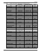
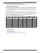
Table Of Contents
- 1.0 Introduction
- 2.0 Liebert iCOM Display Components and Functions
- Figure 2 Liebert iCOM display components
- Table 1 Keyboard icons and functions
- Figure 3 Status menu, large display, graphical view
- Figure 4 Liebert iCOM default screen symbols
- 2.1 Navigating Through the Liebert iCOM Menus
- 3.0 Operation
- 3.1 Single Unit Functions
- 3.2 Motorized Ball Valve in Digital Scroll Units
- 3.3 Temperature Control—Single Source Cooling (No Extra Cooling Coil)
- 3.3.1 Temperature Proportional Band
- 3.3.2 Compressor Control
- Compressor Proportional Bands
- Figure 12 One single-step compressor without unloaders
- Figure 13 Two single-step compressors without unloaders or one compressor with an unloader (two-step)
- Figure 14 Two compressors with unloaders (four-step)
- Figure 15 Digital scroll capacity modulation, 10-100% variable
- Figure 16 Single and dual digital scroll compressor activation points
- Compressor Proportional Bands
- 3.3.3 Chilled Water Control
- 3.4 Temperature Control—Second Cooling Source
- 3.5 Temperature Control—Reheat
- 3.6 Humidity Control
- 3.7 Control Types
- 3.8 Possible Event Notifications
- 3.9 Next Maintenance Calculation
- 4.0 Teamwork
- 5.0 Installing a Liebert iCOM Unit-to-Unit Network
- 5.1 Placement of Cooling Units
- 5.2 U2U Hardware: Cables and Network Switch
- 5.3 Wiring for Unit-to-Unit Communications—U2U
- 5.4 External Communications—Building Management Systems, Liebert SiteScan®
- 6.0 Mounting a Large Display on a Wall
- 7.0 User Menu Parameters
- 8.0 Service Menu Parameters
- Table 23 Setpoints parameters
- Unit Diary—Large Display Only
- Table 24 Unit diary parameters
- Table 25 Standby settings / lead-lag parameters
- Table 26 Maintenance / wellness settings parameters
- Table 27 Diagnostics / service mode parameters
- Table 28 Set alarms parameters
- Table 29 Sensor calibration / setup parameters
- Table 30 System / network setup parameters—large display only
- Table 31 Network setup parameters
- Table 32 Options setup parameters
- Table 33 Service contact info parameters

Operation
35
Table 8 Possible event settings—some events not available in all units
Event
Internal Delay
(Before Action Occurs)
Default Delay / Selectable
(Before Action Occurs)
Type
(default)
MAIN FAN OVERLOAD 2 seconds 5 seconds / 0 – 9999 * ALM
LOSS OF AIRFLOW 3 seconds 3 seconds / 0 – 9999 * ALM
CLOGGED FILTERS 2 seconds 2 seconds / 0 – 9999 * WRN
HIGH ROOM TEMP 1 Min After Fan On 30 seconds / 0 – 9999 Fixed to WRN
LOW ROOM TEMP 1 Min After Fan On 30 seconds / 0 – 9999 Fixed to WRN
HIGH ROOM HUM 1 Min After Fan On 30 seconds / 0 – 9999 Fixed to WRN
LOW ROOM HUM 1 Min After Fan On 30 seconds / 0 – 9999 Fixed to WRN
HIGH TEMP SENSOR A 1 Min After Fan On 30 seconds / 0 – 9999 Fixed to WRN
LOW TEMP SENSOR A 1 Min After Fan On 30 seconds / 0 – 9999 Fixed to WRN
HIGH HUM SENSOR A 1 Min After Fan On 30 seconds / 0 – 9999 Fixed to WRN
LOW HUM SENSOR A 1 Min After Fan On 30 seconds / 0 – 9999 Fixed to WRN
COMP 1 OVERLOAD Internal Calc. no ALM
COMP 2 OVERLOAD Internal Calc. no ALM
COMP 1 HIGH PRESSURE Internal Calc. no ALM
COMP 2 HIGH PRESSURE Internal Calc. no ALM
COMP 1 LOW PRESSURE Internal Calc. no ALM
COMP 2 LOW PRESSURE Internal Calc. no ALM
COMP 1 PUMPDOWN FAIL Internal Calc. no ALM
COMP 2 PUMPDOWN FAIL Internal Calc. no ALM
DIG SCROLL1 HIGH TEMP Internal Calc. no ALM
DIG SCROLL2 HIGH TEMP Internal Calc. no ALM
EL HEAT HIGH TEMP 5 Sec 0 sec / 0 – 9999 WRN
WORKING HRS EXCEEDED 0 Sec 0 sec / 0 – 9999 Fixed to WRN
SMOKE DETECTED 2 Sec 2 sec / 0 – 9999 * ALM
WATER UNDER FLOOR 2 Sec 2 sec / 0 – 9999 * ALM
COND PUMP-HIGH WATER 2 Sec 2 sec / 0 – 9999 * ALM
LOSS OF FLOW
5 Sec
Reset Delay: 10 Sec
2 sec / 0 – 9999 * ALM
STBY GLYCOL PUMP ON 2 Sec 2 sec / 0 – 9999 * ALM
STANDBY UNIT ON 2 Sec 2 sec / 0 – 9999 * ALM
HUMIDIFIER PROBLEM 2 Sec 2 sec / 0 – 9999 * ALM
NO CONNECTION w/Unit1 Internal Calc. - WRN
UNIT X DISCONNECTED Internal Calc. - WRN
LOSS OF POWER 0 Sec No ALM
CUSTOMER INPUT 1 2 Sec 2 sec / 0 – 9999 * ALM
CUSTOMER INPUT 2 2 Sec 2 sec / 0 – 9999 * ALM
CUSTOMER INPUT 3 2 Sec 2 sec / 0 – 9999 * ALM
CUSTOMER INPUT 4 2 Sec 2 sec / 0 – 9999 * ALM
CALL SERVICE 2 Sec 2 sec / 0 – 9999 * MSG
HIGH TEMPERATURE 2 Sec 2 sec / 0 – 9999 * MSG
LOSS OF AIR BLOWER 1 2 Sec 2 sec / 0 – 9999 * ALM
REHEAT LOCKOUT 2 Sec 2 sec / 0 – 9999 * WRN
HUMIDIFIER LOCKOUT 2 Sec 2 sec / 0 – 9999 * WRN
FC LOCKOUT 2 Sec 2 sec / 0 – 9999 * WRN
COMPRESSOR(S) LOCKOUT 2 Sec 2 sec / 0 – 9999 * WRN
COMP 1 SHORT CYCLE 0 Sec 0 - 9999 MSG
COMP 2 SHORT CYCLE 0 Sec 0 - 9999 MSG