
Intelligent Communications & Monitoring System User Manual
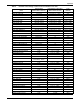
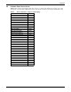
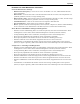
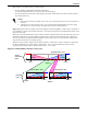
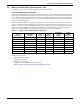
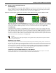
Table Of Contents
- 1.0 Introduction
- 2.0 Liebert iCOM Display Components and Functions
- Figure 2 Liebert iCOM display components
- Table 1 Keyboard icons and functions
- Figure 3 Status menu, large display, graphical view
- Figure 4 Liebert iCOM default screen symbols
- 2.1 Navigating Through the Liebert iCOM Menus
- 3.0 Operation
- 3.1 Single Unit Functions
- 3.2 Motorized Ball Valve in Digital Scroll Units
- 3.3 Temperature Control—Single Source Cooling (No Extra Cooling Coil)
- 3.3.1 Temperature Proportional Band
- 3.3.2 Compressor Control
- Compressor Proportional Bands
- Figure 12 One single-step compressor without unloaders
- Figure 13 Two single-step compressors without unloaders or one compressor with an unloader (two-step)
- Figure 14 Two compressors with unloaders (four-step)
- Figure 15 Digital scroll capacity modulation, 10-100% variable
- Figure 16 Single and dual digital scroll compressor activation points
- Compressor Proportional Bands
- 3.3.3 Chilled Water Control
- 3.4 Temperature Control—Second Cooling Source
- 3.5 Temperature Control—Reheat
- 3.6 Humidity Control
- 3.7 Control Types
- 3.8 Possible Event Notifications
- 3.9 Next Maintenance Calculation
- 4.0 Teamwork
- 5.0 Installing a Liebert iCOM Unit-to-Unit Network
- 5.1 Placement of Cooling Units
- 5.2 U2U Hardware: Cables and Network Switch
- 5.3 Wiring for Unit-to-Unit Communications—U2U
- 5.4 External Communications—Building Management Systems, Liebert SiteScan®
- 6.0 Mounting a Large Display on a Wall
- 7.0 User Menu Parameters
- 8.0 Service Menu Parameters
- Table 23 Setpoints parameters
- Unit Diary—Large Display Only
- Table 24 Unit diary parameters
- Table 25 Standby settings / lead-lag parameters
- Table 26 Maintenance / wellness settings parameters
- Table 27 Diagnostics / service mode parameters
- Table 28 Set alarms parameters
- Table 29 Sensor calibration / setup parameters
- Table 30 System / network setup parameters—large display only
- Table 31 Network setup parameters
- Table 32 Options setup parameters
- Table 33 Service contact info parameters
Operation
36
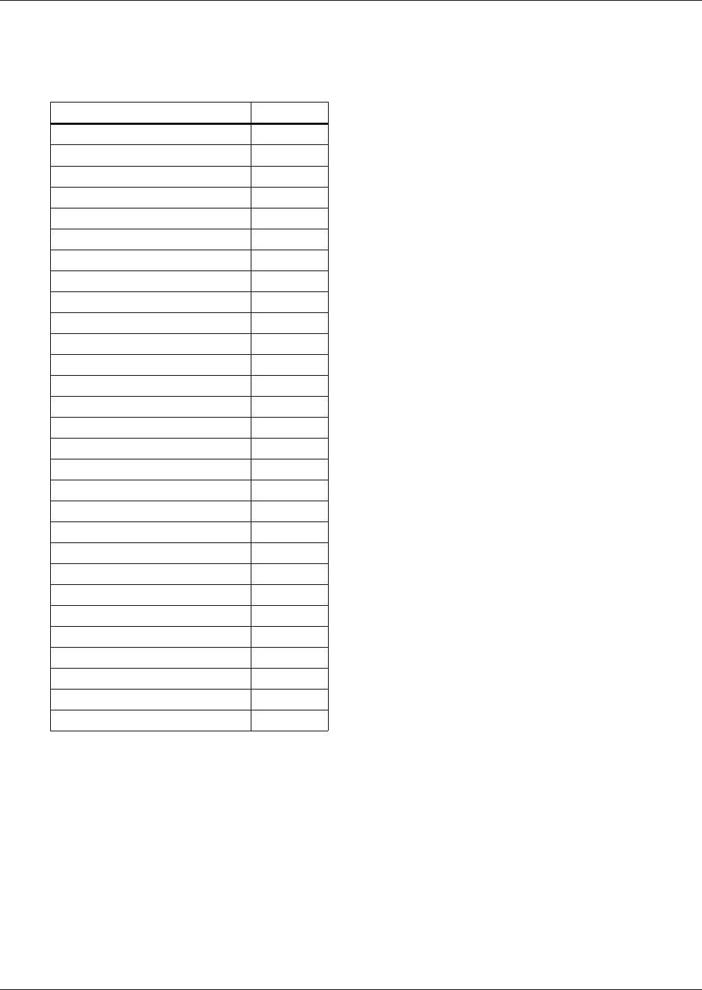
3.8 POSSIBLE EVENT NOTIFICATIONS
Table 9 lists alarms and warnings that may occur in a cooling unit. When any of these occur, they
will appear on the Liebert iCOM Status menu and will be recorded in the Liebert iCOM Event log.
Table 9 Event notifications—large or small display
Event Type
COMP 1 HRS EXCEEDED WRN
COMP 2 HRS EXCEEDED WRN
EL HEAT1 HRS EXCEEDED WRN
EL HEAT2 HRS EXCEEDED WRN
EL HEAT3 HRS EXCEEDED WRN
FC HRS EXCEEDED WRN
GENERAL ALARM ALM
GLYCOL TEMP SENSOR WRN
HIGH CW TEMP WRN
HUM HRS EXCEEDED WRN
HUMIDIFIER PROBLEM —
HW/HG HRS EXCEEDED WRN
LOSS OF CW FLOW WRN
NETWORK FAILURE WRN
ON-OFF KEY DISABLED WRN
POWER ON MSG
POWER OFF MSG
ROOM SENSOR FAILURE ALM
UNIT DISABLED MSG
UNIT HRS EXCEEDED WRN
UNIT ON MSG
UNIT OFF MSG
UNIT DISABLED MSG
UNIT SHUTDOWN MSG
UNIT SYNCHRONIZATION MSG
SENSOR A FAILURE WRN
SLEEP MODE MSG
STANDBY MODE MSG
SUPPLY SENSOR FAILURE WRN