
Intelligent Communications & Monitoring System User Manual
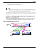
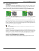
Table Of Contents
- 1.0 Introduction
- 2.0 Liebert iCOM Display Components and Functions
- Figure 2 Liebert iCOM display components
- Table 1 Keyboard icons and functions
- Figure 3 Status menu, large display, graphical view
- Figure 4 Liebert iCOM default screen symbols
- 2.1 Navigating Through the Liebert iCOM Menus
- 3.0 Operation
- 3.1 Single Unit Functions
- 3.2 Motorized Ball Valve in Digital Scroll Units
- 3.3 Temperature Control—Single Source Cooling (No Extra Cooling Coil)
- 3.3.1 Temperature Proportional Band
- 3.3.2 Compressor Control
- Compressor Proportional Bands
- Figure 12 One single-step compressor without unloaders
- Figure 13 Two single-step compressors without unloaders or one compressor with an unloader (two-step)
- Figure 14 Two compressors with unloaders (four-step)
- Figure 15 Digital scroll capacity modulation, 10-100% variable
- Figure 16 Single and dual digital scroll compressor activation points
- Compressor Proportional Bands
- 3.3.3 Chilled Water Control
- 3.4 Temperature Control—Second Cooling Source
- 3.5 Temperature Control—Reheat
- 3.6 Humidity Control
- 3.7 Control Types
- 3.8 Possible Event Notifications
- 3.9 Next Maintenance Calculation
- 4.0 Teamwork
- 5.0 Installing a Liebert iCOM Unit-to-Unit Network
- 5.1 Placement of Cooling Units
- 5.2 U2U Hardware: Cables and Network Switch
- 5.3 Wiring for Unit-to-Unit Communications—U2U
- 5.4 External Communications—Building Management Systems, Liebert SiteScan®
- 6.0 Mounting a Large Display on a Wall
- 7.0 User Menu Parameters
- 8.0 Service Menu Parameters
- Table 23 Setpoints parameters
- Unit Diary—Large Display Only
- Table 24 Unit diary parameters
- Table 25 Standby settings / lead-lag parameters
- Table 26 Maintenance / wellness settings parameters
- Table 27 Diagnostics / service mode parameters
- Table 28 Set alarms parameters
- Table 29 Sensor calibration / setup parameters
- Table 30 System / network setup parameters—large display only
- Table 31 Network setup parameters
- Table 32 Options setup parameters
- Table 33 Service contact info parameters

Operation
37
3.9 Next Maintenance Calculation
The next maintenance calculation, as well as the included diagnostics feature, will help run the cool-
ing unit optimally to ensure minimum component stress resulting in maximum reliability. The diag-
nostics will help the service engineer evaluate the unit’s operation, reading back operational data
since the last maintenance.
3.9.1 Calculation of Next Maintenance and Diagnostics
The following components are included in the calculation, each one individually:
•Fan(s)
• Compressor 1
• Compressor 2
• Electric Heaters
• Humidifier
For each individual component, the next maintenance will be calculated from the following parame-
ters:
• Standard service interval (1, 2 or 4 times a year) (to be set)
• Working hours (counted)
• Number of starts (counted)
• Average running time (calculated)
• Optimum number of starts per hour (to be set)
• Maximum number of starts per hour (to be set)
• Maximum bonus to enlarge time to next maintenance (to be set)
• Maximum penalty to reduce time to next maintenance (to be set)
Calculating Unit Wellness
Liebert iCOM keeps tabs on the condition of a cooling unit, determining its wellness and projecting
when service will be needed, for the entire unit as well as for individual components. This assists in
scheduling maintenance calls and helps pinpoint components likely to require service.
Liebert iCOM displays a graphic for needed maintenance. It begins with the standard maintenance
interval—12 months, six months or three months—and adjusts that based on its calculation of compo-
nents’ wellness.
To calculate wellness, Liebert iCOM keeps a running total of component working hours and the num-
ber of times it has been started. Liebert iCOM relates that data to the optimum/maximum starts per
hour. Accordingly, Liebert iCOM will increase or decrease the time before the next service call will be
needed.
The more frequently a component starts, the sooner it is likely to need maintenance. If, for example, a
unit’s fan runs continuously, but it’s compressor starts and stops often, Liebert iCOM records that
and calls for maintenance based on the compressor’s wellness factor.
Alarms and warnings, such as clogged filters or high or low pressure, reduce the time till the next
maintenance to zero. If the alarm is cleared and reset, Liebert iCOM recalculates wellness. It begins
with the pre-alarm maintenance time and factors in the alarm.