
Intelligent Communications & Monitoring System User Manual
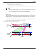
Table Of Contents
- 1.0 Introduction
- 2.0 Liebert iCOM Display Components and Functions
- Figure 2 Liebert iCOM display components
- Table 1 Keyboard icons and functions
- Figure 3 Status menu, large display, graphical view
- Figure 4 Liebert iCOM default screen symbols
- 2.1 Navigating Through the Liebert iCOM Menus
- 3.0 Operation
- 3.1 Single Unit Functions
- 3.2 Motorized Ball Valve in Digital Scroll Units
- 3.3 Temperature Control—Single Source Cooling (No Extra Cooling Coil)
- 3.3.1 Temperature Proportional Band
- 3.3.2 Compressor Control
- Compressor Proportional Bands
- Figure 12 One single-step compressor without unloaders
- Figure 13 Two single-step compressors without unloaders or one compressor with an unloader (two-step)
- Figure 14 Two compressors with unloaders (four-step)
- Figure 15 Digital scroll capacity modulation, 10-100% variable
- Figure 16 Single and dual digital scroll compressor activation points
- Compressor Proportional Bands
- 3.3.3 Chilled Water Control
- 3.4 Temperature Control—Second Cooling Source
- 3.5 Temperature Control—Reheat
- 3.6 Humidity Control
- 3.7 Control Types
- 3.8 Possible Event Notifications
- 3.9 Next Maintenance Calculation
- 4.0 Teamwork
- 5.0 Installing a Liebert iCOM Unit-to-Unit Network
- 5.1 Placement of Cooling Units
- 5.2 U2U Hardware: Cables and Network Switch
- 5.3 Wiring for Unit-to-Unit Communications—U2U
- 5.4 External Communications—Building Management Systems, Liebert SiteScan®
- 6.0 Mounting a Large Display on a Wall
- 7.0 User Menu Parameters
- 8.0 Service Menu Parameters
- Table 23 Setpoints parameters
- Unit Diary—Large Display Only
- Table 24 Unit diary parameters
- Table 25 Standby settings / lead-lag parameters
- Table 26 Maintenance / wellness settings parameters
- Table 27 Diagnostics / service mode parameters
- Table 28 Set alarms parameters
- Table 29 Sensor calibration / setup parameters
- Table 30 System / network setup parameters—large display only
- Table 31 Network setup parameters
- Table 32 Options setup parameters
- Table 33 Service contact info parameters

Operation
38
Parameters for Next Maintenance Calculation
General Maintenance Settings
• Maintenance Frequency—can be set as one to 12 months or to zero, which disables mainte-
nance calculation
• Max. Bonus—increases the time to next maintenance with the set value, if all components run
optimally (number of starts, average running time)
• Max. Penalty value—decreases the time to next maintenance with the set value, if some compo-
nents run in non-optimum way (number of starts, average running time)
• Last Maintenance—date can be set from service-engineer; informational
• Service-Engineer—name of the service engineer; editable
• Reset—puts all counters of all components, such as (motor, compressors, heaters and humidifier),
at zero and starts a new maintenance calculation (reset to be done after maintenance)
Fans / Heaters / Humidifier Settings and Diagnostics
• Number of starts and Working hours are counted separately since the last maintenance. Total
working hours can be read in the standard working hours window (customer window).
• Average Working Hours is the calculation, resulting from starts and working hours.
• Starts per Day Optimum is the number of starts considered as optimum.
• Starts per Day Worst is the number of starts considered as hunting (worst case).
• Number of Alarms counts the alarms, happened between two service intervals.
• Actual Bonus is calculated from number of starts and average working time. Can be positive
(bonus) or negative (penalty). This value influences the time remaining to the next maintenance.
Compressor 1 / 2 Settings and Diagnostics
• Number of starts and Working hours are individually counted since the last maintenance. Total
working hours can be read in the standard working hours window (customer window).
• Average Working Hours is the calculation, resulting from starts and working hours.
• Starts per Day Optimum is the number of starts considered as optimum.
• Starts per Day Worst is the number of starts considered as hunting (worst case).
• Number of HP Alarms counts the high-pressure alarms, happened between 2 service intervals.
• Number of LP Alarms counts the low-pressure alarms, happened between 2 service intervals.
• Number of TH Alarms counts the thermal protection alarms, happened between 2 service inter-
vals.
• Actual Bonus is calculated from number of starts and average working time. Can be positive
(bonus) or negative (penalty). This value influences the time remaining to the next maintenance.