
Intelligent Communications & Monitoring System User Manual
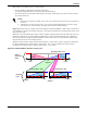
Table Of Contents
- 1.0 Introduction
- 2.0 Liebert iCOM Display Components and Functions
- Figure 2 Liebert iCOM display components
- Table 1 Keyboard icons and functions
- Figure 3 Status menu, large display, graphical view
- Figure 4 Liebert iCOM default screen symbols
- 2.1 Navigating Through the Liebert iCOM Menus
- 3.0 Operation
- 3.1 Single Unit Functions
- 3.2 Motorized Ball Valve in Digital Scroll Units
- 3.3 Temperature Control—Single Source Cooling (No Extra Cooling Coil)
- 3.3.1 Temperature Proportional Band
- 3.3.2 Compressor Control
- Compressor Proportional Bands
- Figure 12 One single-step compressor without unloaders
- Figure 13 Two single-step compressors without unloaders or one compressor with an unloader (two-step)
- Figure 14 Two compressors with unloaders (four-step)
- Figure 15 Digital scroll capacity modulation, 10-100% variable
- Figure 16 Single and dual digital scroll compressor activation points
- Compressor Proportional Bands
- 3.3.3 Chilled Water Control
- 3.4 Temperature Control—Second Cooling Source
- 3.5 Temperature Control—Reheat
- 3.6 Humidity Control
- 3.7 Control Types
- 3.8 Possible Event Notifications
- 3.9 Next Maintenance Calculation
- 4.0 Teamwork
- 5.0 Installing a Liebert iCOM Unit-to-Unit Network
- 5.1 Placement of Cooling Units
- 5.2 U2U Hardware: Cables and Network Switch
- 5.3 Wiring for Unit-to-Unit Communications—U2U
- 5.4 External Communications—Building Management Systems, Liebert SiteScan®
- 6.0 Mounting a Large Display on a Wall
- 7.0 User Menu Parameters
- 8.0 Service Menu Parameters
- Table 23 Setpoints parameters
- Unit Diary—Large Display Only
- Table 24 Unit diary parameters
- Table 25 Standby settings / lead-lag parameters
- Table 26 Maintenance / wellness settings parameters
- Table 27 Diagnostics / service mode parameters
- Table 28 Set alarms parameters
- Table 29 Sensor calibration / setup parameters
- Table 30 System / network setup parameters—large display only
- Table 31 Network setup parameters
- Table 32 Options setup parameters
- Table 33 Service contact info parameters

Teamwork
39
4.0 TEAMWORK
Unit-2-Unit (U2U) Communications via a private network will allow the following functions to be
placed into operation when the requirement exists. The user must install the correct hardware
(see 5.0 - Installing a Liebert iCOM Unit-to-Unit Network) and properly program the units for
the selected functionality.
The Liebert iCOM network can perform the following functions:
The Teamwork Mode functions allow for multiple stages of cooling/heating and humidifica-
tion/dehumidification. Teamwork Mode can be used to prevent environmental units from “fighting,”
where one environmental unit might be cooling while another unit is heating.
The Standby (Lead/Lag) function allows one or more units to be set as “Running” and “Standby” for
activation in case of an alarm. This function also allows the units to be programmed in a rotation to
help ensure “Standby” unit operation.
The Cascade Operation function allows additional units to be staged-on based on the temperature
or humidity requirement.
4.1 Teamwork Modes
Groups of cooling units connected to a network can be set up to work together in any of three team-
work modes: No Teamwork, Teamwork Mode 1 and Teamwork Mode 2. All Liebert iCOM-controlled
cooling units on a network must be set to run in the same Teamwork mode.
4.1.1 Application of Teamwork Modes
• No Teamwork: Multiple zones in one room.
• Teamwork Mode 1: Balanced load (small groups of units inside the same environment)
• Teamwork Mode 2: Unbalanced load (large rooms, not all units will have the same load) (work
well for most applications)
All units in a network will run in the same Teamwork Mode.
4.1.2 No Teamwork
All cooling units work independently, responding to their own sensors.
Standby function and unit rotation are possible, but cascading is not (see Standby and Cascade on
page 41). Autoset will not adjust the proportional band in Teamwork mode No.
4.1.3 Teamwork Mode 1
Teamwork Mode 1 works best in small rooms with balanced heat loads. This mode does not operate
based on the most demanding unit on the network. The return temperature and humidity sensor
readings of all units in operation (fan on) are averaged by the master unit, Unit #1, and used for con-
trol. The master unit will send the performance requests unitwise according to unit numbers, rotated
by one unit every 24 hours.
In this teamwork mode most of the parameters are shared; if set in any one of the units, all other
units will follow with the same settings. AutoSet will adjust the proportional band in Teamwork
Mode 1, see 3.3.1 - Temperature Proportional Band.
The master unit evenly divides the system proportional band among the number of available units.
Each unit will receive instruction on how to operate from the master unit based on how far the system
deviates from the setpoints.