
Intelligent Communications & Monitoring System User Manual
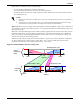
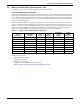
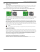
Table Of Contents
- 1.0 Introduction
- 2.0 Liebert iCOM Display Components and Functions
- Figure 2 Liebert iCOM display components
- Table 1 Keyboard icons and functions
- Figure 3 Status menu, large display, graphical view
- Figure 4 Liebert iCOM default screen symbols
- 2.1 Navigating Through the Liebert iCOM Menus
- 3.0 Operation
- 3.1 Single Unit Functions
- 3.2 Motorized Ball Valve in Digital Scroll Units
- 3.3 Temperature Control—Single Source Cooling (No Extra Cooling Coil)
- 3.3.1 Temperature Proportional Band
- 3.3.2 Compressor Control
- Compressor Proportional Bands
- Figure 12 One single-step compressor without unloaders
- Figure 13 Two single-step compressors without unloaders or one compressor with an unloader (two-step)
- Figure 14 Two compressors with unloaders (four-step)
- Figure 15 Digital scroll capacity modulation, 10-100% variable
- Figure 16 Single and dual digital scroll compressor activation points
- Compressor Proportional Bands
- 3.3.3 Chilled Water Control
- 3.4 Temperature Control—Second Cooling Source
- 3.5 Temperature Control—Reheat
- 3.6 Humidity Control
- 3.7 Control Types
- 3.8 Possible Event Notifications
- 3.9 Next Maintenance Calculation
- 4.0 Teamwork
- 5.0 Installing a Liebert iCOM Unit-to-Unit Network
- 5.1 Placement of Cooling Units
- 5.2 U2U Hardware: Cables and Network Switch
- 5.3 Wiring for Unit-to-Unit Communications—U2U
- 5.4 External Communications—Building Management Systems, Liebert SiteScan®
- 6.0 Mounting a Large Display on a Wall
- 7.0 User Menu Parameters
- 8.0 Service Menu Parameters
- Table 23 Setpoints parameters
- Unit Diary—Large Display Only
- Table 24 Unit diary parameters
- Table 25 Standby settings / lead-lag parameters
- Table 26 Maintenance / wellness settings parameters
- Table 27 Diagnostics / service mode parameters
- Table 28 Set alarms parameters
- Table 29 Sensor calibration / setup parameters
- Table 30 System / network setup parameters—large display only
- Table 31 Network setup parameters
- Table 32 Options setup parameters
- Table 33 Service contact info parameters
Teamwork
40
The number of available units is calculated like:
• In non-standby configuration: all units with fan on
• In typical standby function (no cascade): all units with fan on
• In cascade mode: all units that could operate (no alarm, which forces the unit to switch off, unit
not switched off, etc.)
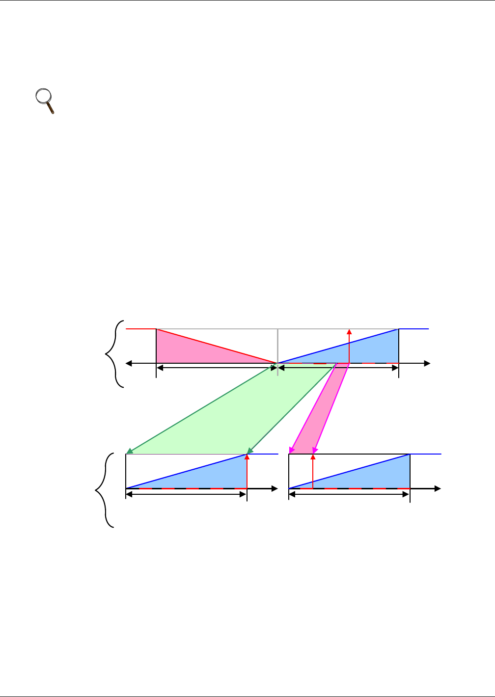
Figure 23 shows how two cooling units work together in Teamwork Mode 1. Since Unit 1 and Unit 2
are available to operate, the master unit, Unit 1, averages the temperature and humidity sensor read-
ings from each unit.
The master unit determines that a 60% call for cooling is required for the system. Since there are two
available cooling units, each unit makes up half of the system proportional band; Unit 1 handles 0-
50% system call for cooling and Unit 2 handles 51-100%. For every 1% system call for cooling, each
unit provides 2% of its total cooling capacity.
The 60% system call for cooling exceeds the 50% Unit 1 can provide, so Unit 1 operates at full capac-
ity. The remaining 10% system call for cooling (60% - 50% = 10%) is handled by Unit 2. Unit 2
responds by operating at 20% cooling capacity (50% ÷ 10% = 20%).
Figure 23 Teamwork Mode 1 with two cooling units
NOTE
1. Proportional actuators (chilled water valve, free-cooling actuator) are driven in parallel in
all units.
2. Changeover to second cooling source, low limit during dehumidification and low supply
limit control air local functions, managed from each unit independently.
Heating
-Temp
+
Temp
System Deviation : 60%
0%
Setpoint
½ Proportional Band½ Proportional Band
+ 100%- 100 %
+ Temp
+ 100%+ 100%
0%
Setpoint
Unit2 Deviation: 20%Unit1 Deviation: 100%
0%
Setpoint
½ Proportional Band½ Proportional Band
Cooling Cooling
Cooling
System
Proportional
Band
+ Temp
Individual
Units