
Intelligent Communications & Monitoring System User Manual
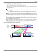
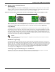
Table Of Contents
- 1.0 Introduction
- 2.0 Liebert iCOM Display Components and Functions
- Figure 2 Liebert iCOM display components
- Table 1 Keyboard icons and functions
- Figure 3 Status menu, large display, graphical view
- Figure 4 Liebert iCOM default screen symbols
- 2.1 Navigating Through the Liebert iCOM Menus
- 3.0 Operation
- 3.1 Single Unit Functions
- 3.2 Motorized Ball Valve in Digital Scroll Units
- 3.3 Temperature Control—Single Source Cooling (No Extra Cooling Coil)
- 3.3.1 Temperature Proportional Band
- 3.3.2 Compressor Control
- Compressor Proportional Bands
- Figure 12 One single-step compressor without unloaders
- Figure 13 Two single-step compressors without unloaders or one compressor with an unloader (two-step)
- Figure 14 Two compressors with unloaders (four-step)
- Figure 15 Digital scroll capacity modulation, 10-100% variable
- Figure 16 Single and dual digital scroll compressor activation points
- Compressor Proportional Bands
- 3.3.3 Chilled Water Control
- 3.4 Temperature Control—Second Cooling Source
- 3.5 Temperature Control—Reheat
- 3.6 Humidity Control
- 3.7 Control Types
- 3.8 Possible Event Notifications
- 3.9 Next Maintenance Calculation
- 4.0 Teamwork
- 5.0 Installing a Liebert iCOM Unit-to-Unit Network
- 5.1 Placement of Cooling Units
- 5.2 U2U Hardware: Cables and Network Switch
- 5.3 Wiring for Unit-to-Unit Communications—U2U
- 5.4 External Communications—Building Management Systems, Liebert SiteScan®
- 6.0 Mounting a Large Display on a Wall
- 7.0 User Menu Parameters
- 8.0 Service Menu Parameters
- Table 23 Setpoints parameters
- Unit Diary—Large Display Only
- Table 24 Unit diary parameters
- Table 25 Standby settings / lead-lag parameters
- Table 26 Maintenance / wellness settings parameters
- Table 27 Diagnostics / service mode parameters
- Table 28 Set alarms parameters
- Table 29 Sensor calibration / setup parameters
- Table 30 System / network setup parameters—large display only
- Table 31 Network setup parameters
- Table 32 Options setup parameters
- Table 33 Service contact info parameters

Installing a Liebert iCOM Unit-to-Unit Network
42
5.0 INSTALLING A LIEBERT ICOM UNIT-TO-UNIT NETWORK
Connecting multiple Liebert iCOM-controlled cooling units in an Ethernet Unit-to-Unit (U2U) net-
work enables the units to work together to achieve efficient cooling and humidity control of the condi-
tioned space. Networking enables setting up the cooling units to exchange data for various modes of
operation:
• Teamwork
• Lead/Lag-Standby
• Rotation
• Cascade
However the cooling units are set up, a large display may be used to control and view the operational
status of individual units or of the entire system.
5.1 Placement of Cooling Units
Refer to the cooling unit product manuals for details on installation. Also consider these factors when
planning for installation of cooling units with Liebert iCOM controls:
• heat load in the conditioned space
• cooling air distribution
• number of operating units versus number of standby cooling units
• location of the network switch—An Ethernet cable cannot exceed 328 feet (100m)
5.2 U2U Hardware: Cables and Network Switch
Plan wiring runs for U2U communication when designing the layout of your conditioned space. In
addition to general good wiring practices, take into account:
• Ethernet CAT5 or greater cable is required for interconnecting the units.
• Maximum distance must not exceed 328 feet (100m).
• A device to boost the Ethernet signal may be used to exceed the 328 feet (100m) length limitation.
• Ethernet network should be private—set up only for management and control of the cooling units.
• Keep control and communication cables away from power cables to prevent electromagnetic inter-
ference.
• Do not bend cables to less than four times the diameter of the cable.
• Do not deform cables when securing in bundles or when hanging them.
• Keep cables away from devices that can introduce noise into them, such as machines, fluorescent
lights, and electronics.
• Avoid stretching Ethernet cables—tension when pulling cables should not exceed 25 pounds
(11kg).
• Do not secure Ethernet cables with any method that might damage them; use approved hangers,
such as telephone wire/RG-6 coaxial wire hangers, available at most hardware stores.
Minimum Network Switch Requirements
• IEEE 802.3; IEEE 802.3u
• 10/100 Mbps speed
• Multiple 10/100 RJ-45 ports—one shared; RJ-45 Uplink port
The Liebert vNSA
™
is an approved powered network switch designed to support Liebert iCOM U2U
networks. See Liebert vNSA on page 47 for details.
NOTE
The maximum number of cooling units that may be interconnected is 32.