
Intelligent Communications & Monitoring System User Manual
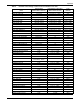
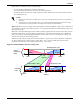
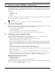
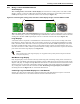
Table Of Contents
- 1.0 Introduction
- 2.0 Liebert iCOM Display Components and Functions
- Figure 2 Liebert iCOM display components
- Table 1 Keyboard icons and functions
- Figure 3 Status menu, large display, graphical view
- Figure 4 Liebert iCOM default screen symbols
- 2.1 Navigating Through the Liebert iCOM Menus
- 3.0 Operation
- 3.1 Single Unit Functions
- 3.2 Motorized Ball Valve in Digital Scroll Units
- 3.3 Temperature Control—Single Source Cooling (No Extra Cooling Coil)
- 3.3.1 Temperature Proportional Band
- 3.3.2 Compressor Control
- Compressor Proportional Bands
- Figure 12 One single-step compressor without unloaders
- Figure 13 Two single-step compressors without unloaders or one compressor with an unloader (two-step)
- Figure 14 Two compressors with unloaders (four-step)
- Figure 15 Digital scroll capacity modulation, 10-100% variable
- Figure 16 Single and dual digital scroll compressor activation points
- Compressor Proportional Bands
- 3.3.3 Chilled Water Control
- 3.4 Temperature Control—Second Cooling Source
- 3.5 Temperature Control—Reheat
- 3.6 Humidity Control
- 3.7 Control Types
- 3.8 Possible Event Notifications
- 3.9 Next Maintenance Calculation
- 4.0 Teamwork
- 5.0 Installing a Liebert iCOM Unit-to-Unit Network
- 5.1 Placement of Cooling Units
- 5.2 U2U Hardware: Cables and Network Switch
- 5.3 Wiring for Unit-to-Unit Communications—U2U
- 5.4 External Communications—Building Management Systems, Liebert SiteScan®
- 6.0 Mounting a Large Display on a Wall
- 7.0 User Menu Parameters
- 8.0 Service Menu Parameters
- Table 23 Setpoints parameters
- Unit Diary—Large Display Only
- Table 24 Unit diary parameters
- Table 25 Standby settings / lead-lag parameters
- Table 26 Maintenance / wellness settings parameters
- Table 27 Diagnostics / service mode parameters
- Table 28 Set alarms parameters
- Table 29 Sensor calibration / setup parameters
- Table 30 System / network setup parameters—large display only
- Table 31 Network setup parameters
- Table 32 Options setup parameters
- Table 33 Service contact info parameters
Installing a Liebert iCOM Unit-to-Unit Network
43
5.3 Wiring for Unit-to-Unit Communications—U2U
Cooling units come from the factory-wired for stand-alone operation.
Liebert iCOM U2U Ethernet Network
The Liebert iCOM U2U network must be isolated from other network traffic. The network switch(es)
that connect Liebert iCOM controls need to be dedicated to supporting only Liebert iCOM communi-
cation. The U2U network cannot be connected to the building or IT network. If network communica-
tion is ever lost (failed network switch, etc.), all Liebert iCOM-controlled cooling units will continue to
operate as independent units.
The Liebert iCOM control can support up to 64 nodes on one network. An input/output board, large
display, and large wall-mount display are each considered one node. Of the 64 nodes that may be con-
nected, no more than 32 may be input/output boards (32 cooling units). A small display is not consid-
ered a node. Small displays connect directly to input/output boards that do not have large displays
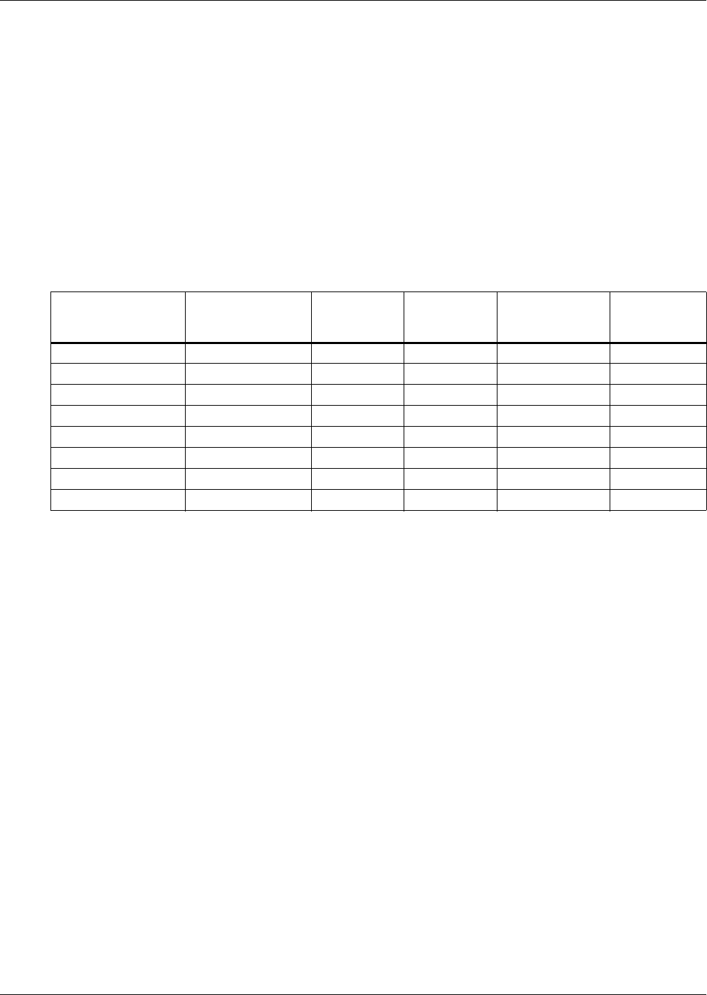
attached to them. The following table illustrates how a network can be configured.
Network communication can be configured during system startup by a Liebert-trained technician. For
technical issues contact:
Liebert Technical Service
1050 Dearborn Drive
Columbus, Ohio 43235
Telephone: 1-800-LIEBSRV (1-800-543-2778)
E-Mail: technicalservice@emersonnetworkpower.com
Table 10 Sample Liebert iCOM network configurations
Sample
Configuration
Input/Output
Boards
Large
Displays
Small
Displays
Wall Mount
Large
Displays
Private
Switch
Required
12020No
22021Yes
33030Yes
42110Yes
58441Yes
6323200Yes
7322755Yes
8 32 0 32 32 Yes