
Intelligent Communications & Monitoring System User Manual
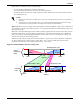
Table Of Contents
- 1.0 Introduction
- 2.0 Liebert iCOM Display Components and Functions
- Figure 2 Liebert iCOM display components
- Table 1 Keyboard icons and functions
- Figure 3 Status menu, large display, graphical view
- Figure 4 Liebert iCOM default screen symbols
- 2.1 Navigating Through the Liebert iCOM Menus
- 3.0 Operation
- 3.1 Single Unit Functions
- 3.2 Motorized Ball Valve in Digital Scroll Units
- 3.3 Temperature Control—Single Source Cooling (No Extra Cooling Coil)
- 3.3.1 Temperature Proportional Band
- 3.3.2 Compressor Control
- Compressor Proportional Bands
- Figure 12 One single-step compressor without unloaders
- Figure 13 Two single-step compressors without unloaders or one compressor with an unloader (two-step)
- Figure 14 Two compressors with unloaders (four-step)
- Figure 15 Digital scroll capacity modulation, 10-100% variable
- Figure 16 Single and dual digital scroll compressor activation points
- Compressor Proportional Bands
- 3.3.3 Chilled Water Control
- 3.4 Temperature Control—Second Cooling Source
- 3.5 Temperature Control—Reheat
- 3.6 Humidity Control
- 3.7 Control Types
- 3.8 Possible Event Notifications
- 3.9 Next Maintenance Calculation
- 4.0 Teamwork
- 5.0 Installing a Liebert iCOM Unit-to-Unit Network
- 5.1 Placement of Cooling Units
- 5.2 U2U Hardware: Cables and Network Switch
- 5.3 Wiring for Unit-to-Unit Communications—U2U
- 5.4 External Communications—Building Management Systems, Liebert SiteScan®
- 6.0 Mounting a Large Display on a Wall
- 7.0 User Menu Parameters
- 8.0 Service Menu Parameters
- Table 23 Setpoints parameters
- Unit Diary—Large Display Only
- Table 24 Unit diary parameters
- Table 25 Standby settings / lead-lag parameters
- Table 26 Maintenance / wellness settings parameters
- Table 27 Diagnostics / service mode parameters
- Table 28 Set alarms parameters
- Table 29 Sensor calibration / setup parameters
- Table 30 System / network setup parameters—large display only
- Table 31 Network setup parameters
- Table 32 Options setup parameters
- Table 33 Service contact info parameters
Installing a Liebert iCOM Unit-to-Unit Network
44
5.3.1 Wiring a Liebert iCOM U2U Network
Small Displays
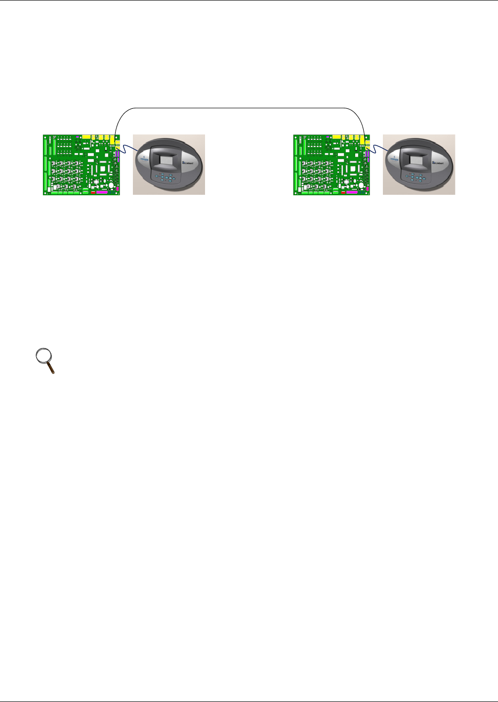
Two cooling units, each with a small display: To network two cooling units, each with a small
display, connect a crossover CAT5 cable between the P64 connectors on each cooling unit’s Liebert
iCOM input/output board. A network switch is not needed (see Figure 24).
Figure 24 Connecting two cooling units, each with a small display using a crossover Ethernet cable
Three or more units with small displays: To network three or more cooling units, each equipped
with a small display, connect a straight-through CAT5 Ethernet cable from the P64 connector on each
cooling unit’s Liebert iCOM input/output board to a common network switch (see Figure 26).
Large Displays
A network switch is required to enable Ethernet communication on one or more cooling units with
large displays. Each cooling unit with a large display requires two straight-through Ethernet cables
from a network switch. One cable connects to port P64 on the Liebert iCOM input/output board and
the other straight-through cable connects to the female-female coupler provided with the unit. Con-
nect the red crossover cable, which is provided with the cooling unit, between the coupler and the P64
port on the back of the large display (see Figure 28).
Wall-Mount Large Display
Only large displays can be used for remotely monitoring and controlling cooling units connected on
the same network. Each wall-mount large display requires 120V input power; Liebert provides an AC
adapter wall plug. A straight-through Ethernet cable must be connected between the network switch
and the P64 port on the back of the display. This will enable control and monitoring capabilities to
any cooling unit connected to the network. See 6.0 - Mounting a Large Display on a Wall for
mounting details and Figure 31 for wall-mount dimensions.
Combining Large and Small Displays on a U2U Network
Setting up a network of cooling units equipped with large and small displays requires a network
switch. The controls are to be connected to the switch as described above.
NOTE
Only cooling units with large displays are supplied with a female-female coupler inside the
unit from the factory.