
Intelligent Communications & Monitoring System User Manual
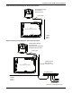
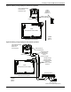
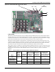
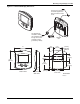
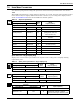
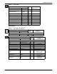
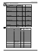
Table Of Contents
- 1.0 Introduction
- 2.0 Liebert iCOM Display Components and Functions
- Figure 2 Liebert iCOM display components
- Table 1 Keyboard icons and functions
- Figure 3 Status menu, large display, graphical view
- Figure 4 Liebert iCOM default screen symbols
- 2.1 Navigating Through the Liebert iCOM Menus
- 3.0 Operation
- 3.1 Single Unit Functions
- 3.2 Motorized Ball Valve in Digital Scroll Units
- 3.3 Temperature Control—Single Source Cooling (No Extra Cooling Coil)
- 3.3.1 Temperature Proportional Band
- 3.3.2 Compressor Control
- Compressor Proportional Bands
- Figure 12 One single-step compressor without unloaders
- Figure 13 Two single-step compressors without unloaders or one compressor with an unloader (two-step)
- Figure 14 Two compressors with unloaders (four-step)
- Figure 15 Digital scroll capacity modulation, 10-100% variable
- Figure 16 Single and dual digital scroll compressor activation points
- Compressor Proportional Bands
- 3.3.3 Chilled Water Control
- 3.4 Temperature Control—Second Cooling Source
- 3.5 Temperature Control—Reheat
- 3.6 Humidity Control
- 3.7 Control Types
- 3.8 Possible Event Notifications
- 3.9 Next Maintenance Calculation
- 4.0 Teamwork
- 5.0 Installing a Liebert iCOM Unit-to-Unit Network
- 5.1 Placement of Cooling Units
- 5.2 U2U Hardware: Cables and Network Switch
- 5.3 Wiring for Unit-to-Unit Communications—U2U
- 5.4 External Communications—Building Management Systems, Liebert SiteScan®
- 6.0 Mounting a Large Display on a Wall
- 7.0 User Menu Parameters
- 8.0 Service Menu Parameters
- Table 23 Setpoints parameters
- Unit Diary—Large Display Only
- Table 24 Unit diary parameters
- Table 25 Standby settings / lead-lag parameters
- Table 26 Maintenance / wellness settings parameters
- Table 27 Diagnostics / service mode parameters
- Table 28 Set alarms parameters
- Table 29 Sensor calibration / setup parameters
- Table 30 System / network setup parameters—large display only
- Table 31 Network setup parameters
- Table 32 Options setup parameters
- Table 33 Service contact info parameters
Installing a Liebert iCOM Unit-to-Unit Network
47
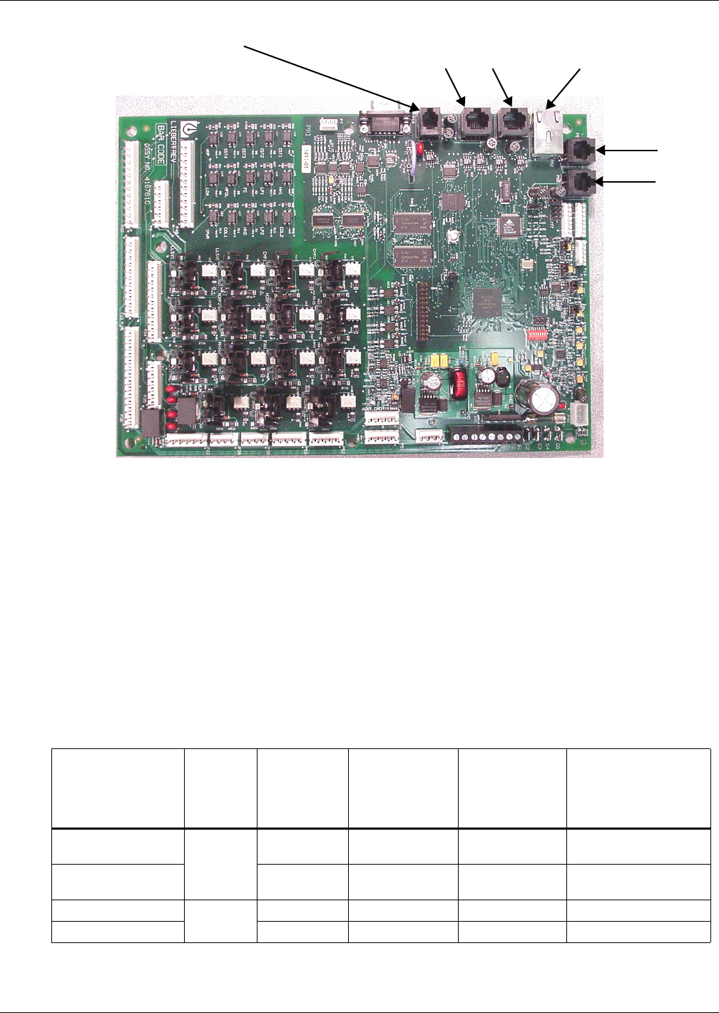
Figure 29 Liebert iCOM input-output control board
Liebert vNSA
The Liebert vNSA is designed to connect multiple Liebert iCOM control devices. The Liebert vNSA
contains either one or two powered industrial rail switches. An optional remote large display can be
attached to the front door as well. All models have a power supply that requires connection to a single
phase 120V or 240VAC power source. The enclosure features a key lock for security.
The Liebert vNSA supports autonegotiation, autopolarity and autocrossing, allowing for the use of
standard network cables for connection to each port, rather than special crossover cables. The switch
detects and makes adjustments for the network's speed and transmission mode, polarity and trans-
mit-and-receive pins. See the Liebert vNSA user manual, SL-18840, for more details.
The number of ports available for connecting Liebert iCOM control devices varies by model as shown
in Table 11. Models with a remote large display attached to the front door utilize one of the available
Ethernet ports in the Liebert vNSA. Models with two switches utilize two ports to connect the
switches.
Table 11 Ports available for connecting Liebert iCOM control devices
Model
Liebert
vNSA With
Remote
Large
Display
Total Number
of Ports
Number of Ports
Used to Connect
Remote Large
Display
Number of Ports
Used to
Interconnect
Switches
Number of Ports
Available to
Connect Liebert iCOM
Control Devices
Liebert vNSA8-Liebert
iCOM
Yes
81 - 7
Liebert vNSA16-
Liebert iCOM
16 1 2 13
Liebert vNSA8
No
8- - 8
Liebert vNSA16 16 - 2 14
P65 P64
(RJ-45 Jack)
P66
P63P61
P67