
Intelligent Communications & Monitoring System User Manual
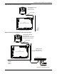
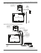
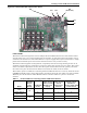
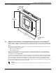
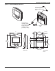
Table Of Contents
- 1.0 Introduction
- 2.0 Liebert iCOM Display Components and Functions
- Figure 2 Liebert iCOM display components
- Table 1 Keyboard icons and functions
- Figure 3 Status menu, large display, graphical view
- Figure 4 Liebert iCOM default screen symbols
- 2.1 Navigating Through the Liebert iCOM Menus
- 3.0 Operation
- 3.1 Single Unit Functions
- 3.2 Motorized Ball Valve in Digital Scroll Units
- 3.3 Temperature Control—Single Source Cooling (No Extra Cooling Coil)
- 3.3.1 Temperature Proportional Band
- 3.3.2 Compressor Control
- Compressor Proportional Bands
- Figure 12 One single-step compressor without unloaders
- Figure 13 Two single-step compressors without unloaders or one compressor with an unloader (two-step)
- Figure 14 Two compressors with unloaders (four-step)
- Figure 15 Digital scroll capacity modulation, 10-100% variable
- Figure 16 Single and dual digital scroll compressor activation points
- Compressor Proportional Bands
- 3.3.3 Chilled Water Control
- 3.4 Temperature Control—Second Cooling Source
- 3.5 Temperature Control—Reheat
- 3.6 Humidity Control
- 3.7 Control Types
- 3.8 Possible Event Notifications
- 3.9 Next Maintenance Calculation
- 4.0 Teamwork
- 5.0 Installing a Liebert iCOM Unit-to-Unit Network
- 5.1 Placement of Cooling Units
- 5.2 U2U Hardware: Cables and Network Switch
- 5.3 Wiring for Unit-to-Unit Communications—U2U
- 5.4 External Communications—Building Management Systems, Liebert SiteScan®
- 6.0 Mounting a Large Display on a Wall
- 7.0 User Menu Parameters
- 8.0 Service Menu Parameters
- Table 23 Setpoints parameters
- Unit Diary—Large Display Only
- Table 24 Unit diary parameters
- Table 25 Standby settings / lead-lag parameters
- Table 26 Maintenance / wellness settings parameters
- Table 27 Diagnostics / service mode parameters
- Table 28 Set alarms parameters
- Table 29 Sensor calibration / setup parameters
- Table 30 System / network setup parameters—large display only
- Table 31 Network setup parameters
- Table 32 Options setup parameters
- Table 33 Service contact info parameters
Installing a Liebert iCOM Unit-to-Unit Network
48
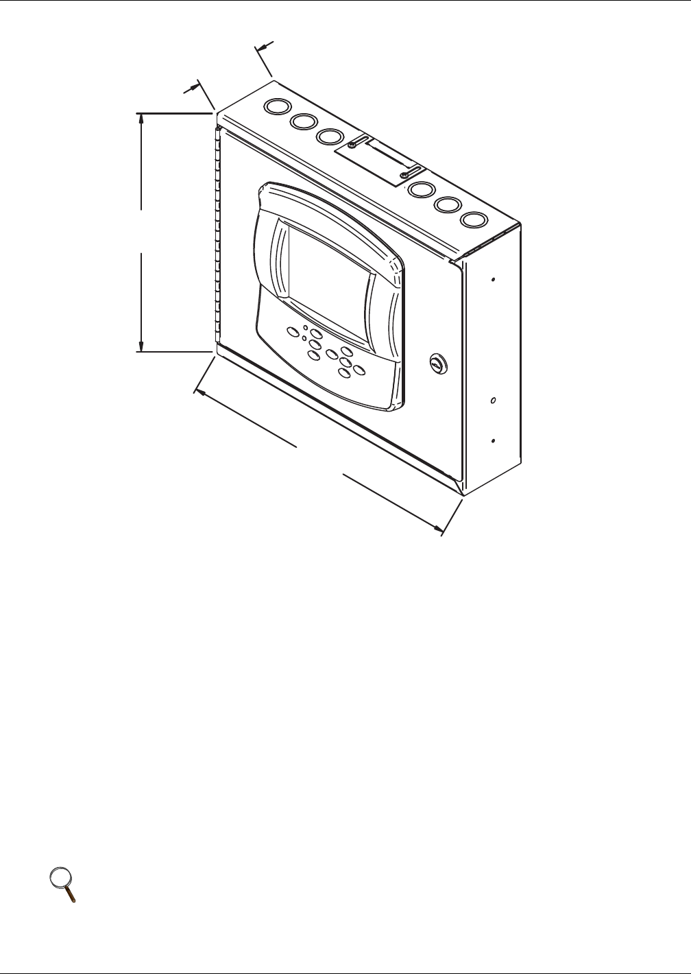
Figure 30 Liebert vNSA with optional remote large display
5.4 External Communications—Building Management Systems, Liebert SiteScan
®
Liebert iCOM is capable of communicating with external monitoring systems, such as Building Man-
agement Systems (BMS), Network Monitoring Systems (NMS), Liebert's SiteScan
®
Web system and
others.
Each Liebert iCOM-controlled cooling unit is equipped with Liebert IntelliSlot plug-in slots for use
with optional communication cards:
• Ethernet Web/SNMP Card
• RS-485 Modbus Card
The hot-swappable plug-in cards provide interfaces supporting open protocols, including Modbus,
HTTP (Web) and SNMP. See the Liebert Web site for the latest supported protocols, Modbus refer-
ence information and SNMP MIB's.
An alternative, limited method of communicating with an existing Liebert SiteScan Web monitoring
system is via twisted-pair cables connected to terminals 77 and 78 on the cooling unit terminal strip.
To use this method, the Liebert IntelliSlot power supply connection to P65 on the iCOM I/O board
must be unplugged, and the factory-supplied 77-78 cable must be connected to P65 (follow Liebert
SiteScan instructions for further connections). The appropriate Liebert iCOM control parameters will
also need to be configured to utilize the terminals.
NOTE
Liebert SiteScan will be limited to legacy parameters when communicating via terminals 77
and 78.
3.298"
(84mm)
12"
(305mm)
14.25"
(362mm)
DPN001136
Rev. 0