
Intelligent Communications & Monitoring System User Manual
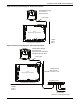
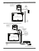
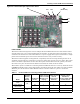
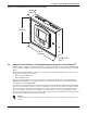
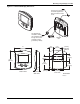
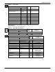
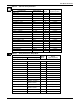
Table Of Contents
- 1.0 Introduction
- 2.0 Liebert iCOM Display Components and Functions
- Figure 2 Liebert iCOM display components
- Table 1 Keyboard icons and functions
- Figure 3 Status menu, large display, graphical view
- Figure 4 Liebert iCOM default screen symbols
- 2.1 Navigating Through the Liebert iCOM Menus
- 3.0 Operation
- 3.1 Single Unit Functions
- 3.2 Motorized Ball Valve in Digital Scroll Units
- 3.3 Temperature Control—Single Source Cooling (No Extra Cooling Coil)
- 3.3.1 Temperature Proportional Band
- 3.3.2 Compressor Control
- Compressor Proportional Bands
- Figure 12 One single-step compressor without unloaders
- Figure 13 Two single-step compressors without unloaders or one compressor with an unloader (two-step)
- Figure 14 Two compressors with unloaders (four-step)
- Figure 15 Digital scroll capacity modulation, 10-100% variable
- Figure 16 Single and dual digital scroll compressor activation points
- Compressor Proportional Bands
- 3.3.3 Chilled Water Control
- 3.4 Temperature Control—Second Cooling Source
- 3.5 Temperature Control—Reheat
- 3.6 Humidity Control
- 3.7 Control Types
- 3.8 Possible Event Notifications
- 3.9 Next Maintenance Calculation
- 4.0 Teamwork
- 5.0 Installing a Liebert iCOM Unit-to-Unit Network
- 5.1 Placement of Cooling Units
- 5.2 U2U Hardware: Cables and Network Switch
- 5.3 Wiring for Unit-to-Unit Communications—U2U
- 5.4 External Communications—Building Management Systems, Liebert SiteScan®
- 6.0 Mounting a Large Display on a Wall
- 7.0 User Menu Parameters
- 8.0 Service Menu Parameters
- Table 23 Setpoints parameters
- Unit Diary—Large Display Only
- Table 24 Unit diary parameters
- Table 25 Standby settings / lead-lag parameters
- Table 26 Maintenance / wellness settings parameters
- Table 27 Diagnostics / service mode parameters
- Table 28 Set alarms parameters
- Table 29 Sensor calibration / setup parameters
- Table 30 System / network setup parameters—large display only
- Table 31 Network setup parameters
- Table 32 Options setup parameters
- Table 33 Service contact info parameters

Mounting a Large Display on a Wall
49
6.0 MOUNTING A LARGE DISPLAY ON A WALL
6.0.1 Location Considerations
Consider these factors before beginning work on a wall-mount installation:
• Power supply—Liebert iCOM requires an electricity source. A factory-supplied 120VAC trans-
former connects to the back of the large display.
• Availability of communication cable—CAT5 Ethernet cable connection on the back of the large
display
• Distance from network switch—maximum of 328 feet (100m)
• Accessible location for personnel
Necessary Mounting Items
• #10 pan head type screws or bolts—quantity 2, field-supplied
• Wall anchors sized for #10 pan head type screws or bolts—quantity 2, field-supplied, if mounting
on drywall or similar surface
Mounting Instructions
1. See Figure 31 for dimensions and mounting arrangements. Mark the wall where screws or bolts
will be inserted to support the large display.
Either of two mounting methods may be used:
a. Secure the back of the large display to the wall by inserting screws or bolts through the
elliptical slots (recommended mounting method), or
b. Insert screws in the wall and use the keyhole-shaped holes on the back of the housing
2. Route the factory-supplied power supply cable and field-supplied CAT5 Ethernet cable through
the wall to the mounting location for connection to the rear of the Liebert iCOM wall-mount
display (see Figure 31).
3. Remove the back of the display by prying it away from the front half of the housing using the coin
slots along the seam.
4. Insert the power and Ethernet cables through slots in the rear of the display (slots are marked).
Leave adequate slack for connections and mounting.
To relieve strain on the connections to the display circuit board:
a. Use the strain-relief slots above the connections on the upper part of the recessed area to hold
the cables.
b. Use a twist tie to secure the cables to the small bridge on the back of the display.
5. Position the display and use either of the following methods to attach the display to the wall:
a. Elliptical Slot Mounting: Insert the #10 pan head screws or bolts through the elliptical
slots and screw into the wall or wall anchors. Tighten firmly.
OR
b. Keyhole Slot Mounting: Insert the #10 pan head screws or bolts into the wall, leaving space
between the screw head and wall to permit hanging the display.
6. Connect the power and Ethernet cables to the display circuit board (the board is marked).
7. Attach the front of the display to the mounted rear panel of the assembly—unit snaps together.