
Intelligent Communications & Monitoring System User Manual
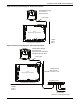
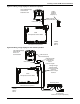
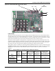
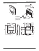
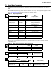
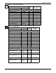
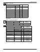
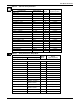
Table Of Contents
- 1.0 Introduction
- 2.0 Liebert iCOM Display Components and Functions
- Figure 2 Liebert iCOM display components
- Table 1 Keyboard icons and functions
- Figure 3 Status menu, large display, graphical view
- Figure 4 Liebert iCOM default screen symbols
- 2.1 Navigating Through the Liebert iCOM Menus
- 3.0 Operation
- 3.1 Single Unit Functions
- 3.2 Motorized Ball Valve in Digital Scroll Units
- 3.3 Temperature Control—Single Source Cooling (No Extra Cooling Coil)
- 3.3.1 Temperature Proportional Band
- 3.3.2 Compressor Control
- Compressor Proportional Bands
- Figure 12 One single-step compressor without unloaders
- Figure 13 Two single-step compressors without unloaders or one compressor with an unloader (two-step)
- Figure 14 Two compressors with unloaders (four-step)
- Figure 15 Digital scroll capacity modulation, 10-100% variable
- Figure 16 Single and dual digital scroll compressor activation points
- Compressor Proportional Bands
- 3.3.3 Chilled Water Control
- 3.4 Temperature Control—Second Cooling Source
- 3.5 Temperature Control—Reheat
- 3.6 Humidity Control
- 3.7 Control Types
- 3.8 Possible Event Notifications
- 3.9 Next Maintenance Calculation
- 4.0 Teamwork
- 5.0 Installing a Liebert iCOM Unit-to-Unit Network
- 5.1 Placement of Cooling Units
- 5.2 U2U Hardware: Cables and Network Switch
- 5.3 Wiring for Unit-to-Unit Communications—U2U
- 5.4 External Communications—Building Management Systems, Liebert SiteScan®
- 6.0 Mounting a Large Display on a Wall
- 7.0 User Menu Parameters
- 8.0 Service Menu Parameters
- Table 23 Setpoints parameters
- Unit Diary—Large Display Only
- Table 24 Unit diary parameters
- Table 25 Standby settings / lead-lag parameters
- Table 26 Maintenance / wellness settings parameters
- Table 27 Diagnostics / service mode parameters
- Table 28 Set alarms parameters
- Table 29 Sensor calibration / setup parameters
- Table 30 System / network setup parameters—large display only
- Table 31 Network setup parameters
- Table 32 Options setup parameters
- Table 33 Service contact info parameters
User Menu Parameters
51
7.0 USER MENU PARAMETERS
User menus report general cooling unit operations and status. The password for the user menu is
1490.
The iCOM control firmware is being updated constantly. As a result, the User menu parameter tables
in this manual may be slightly different than what is shown on your cooling unit's display. Please
check www.liebert.com for the latest iCOM User manual updates.
Spare Part List—Large Display Only
Displays the various Liebert part numbers for all parts in the cooling unit to simplify ordering
replacement parts.
Table 12 Setpoints parameters
Function
Read/
Write
Range
Imperial (metric)
Large Display Small Display
Page 1 of 1
Password PASSWORD W -
Temperature Setpoint TEMP SET W 41-104°F (5-40°C)
Humidity Setpoint HUM SET W
20-80%
(settings lower than 19%
will be forced to 20)
Humidity Control Type HUM CTRL W
Relative, Compensated,
Predictive
Supply Limit SUP LIM W Enabled, Disabled
Supply Limit Temp Value SUP TEMP W 41-77°F (5-25°C)
Backup Temperature
Setpoint
BACK TPS W 41-104°F (5-40°C)
Table 13 Spare part list parameters—large display only
Function
Read/
Write
Range
Imperial (metric)
Large Display Small Display
Page 1 of 1
List of parts N/A R -
Table 14 Event log parameters
Function
Read/
Write
Range
Imperial (metric)
Large Display Small Display
Page 1 of 1
Last 400 events Last 400 events R -
Table 15 View network parameters—large display only*
Function
Read/
Write
Range
Imperial (metric)
Large Display Small Display
Page 1 of 1
Status Unit 1—32 N/A R
AlarmOff, Manual, LocalOff, SystemOff,
AlarmStandby, Standby, TimerOff,
SystemOn, WarningOn, AlarmOn, Timer
* Permits viewing all units connected in a network. Viewable on a large display only.
°C / °F
% RH
SET
EVENT
LOG