
Intelligent Communications & Monitoring System User Manual
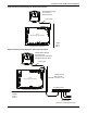
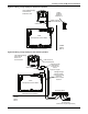
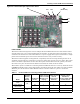
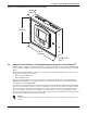
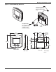
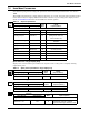
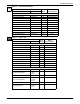
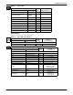
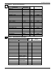
Table Of Contents
- 1.0 Introduction
- 2.0 Liebert iCOM Display Components and Functions
- Figure 2 Liebert iCOM display components
- Table 1 Keyboard icons and functions
- Figure 3 Status menu, large display, graphical view
- Figure 4 Liebert iCOM default screen symbols
- 2.1 Navigating Through the Liebert iCOM Menus
- 3.0 Operation
- 3.1 Single Unit Functions
- 3.2 Motorized Ball Valve in Digital Scroll Units
- 3.3 Temperature Control—Single Source Cooling (No Extra Cooling Coil)
- 3.3.1 Temperature Proportional Band
- 3.3.2 Compressor Control
- Compressor Proportional Bands
- Figure 12 One single-step compressor without unloaders
- Figure 13 Two single-step compressors without unloaders or one compressor with an unloader (two-step)
- Figure 14 Two compressors with unloaders (four-step)
- Figure 15 Digital scroll capacity modulation, 10-100% variable
- Figure 16 Single and dual digital scroll compressor activation points
- Compressor Proportional Bands
- 3.3.3 Chilled Water Control
- 3.4 Temperature Control—Second Cooling Source
- 3.5 Temperature Control—Reheat
- 3.6 Humidity Control
- 3.7 Control Types
- 3.8 Possible Event Notifications
- 3.9 Next Maintenance Calculation
- 4.0 Teamwork
- 5.0 Installing a Liebert iCOM Unit-to-Unit Network
- 5.1 Placement of Cooling Units
- 5.2 U2U Hardware: Cables and Network Switch
- 5.3 Wiring for Unit-to-Unit Communications—U2U
- 5.4 External Communications—Building Management Systems, Liebert SiteScan®
- 6.0 Mounting a Large Display on a Wall
- 7.0 User Menu Parameters
- 8.0 Service Menu Parameters
- Table 23 Setpoints parameters
- Unit Diary—Large Display Only
- Table 24 Unit diary parameters
- Table 25 Standby settings / lead-lag parameters
- Table 26 Maintenance / wellness settings parameters
- Table 27 Diagnostics / service mode parameters
- Table 28 Set alarms parameters
- Table 29 Sensor calibration / setup parameters
- Table 30 System / network setup parameters—large display only
- Table 31 Network setup parameters
- Table 32 Options setup parameters
- Table 33 Service contact info parameters
User Menu Parameters
52
Table 16 Set alarms parameters
Function
Read/
Write
Range
Imperial (metric)
Large Display Small Display
Page 1 of 1
Password PASSWORD W -
Return Sensor Alarms RTN SNSR W Enabled, Disabled
High Return Temperature HI TEMP W 34-210°F (1-99°C)
Low Return Temperature LO TEMP W 34-210°F (1-99°C)
High Return Humidity HI HUM W 1-99%
Low Return Humidity LOW HUM W 1-99%
Sensor A Alarms SENSOR A W Enabled, Disabled
High Temperature Sensor A HI TEMP A W 34-210°F (1-99°C)
Low Temperature Sensor A LO TEMP A W 34-210°F (1-99°C)
High Humidity Sensor A HI HUM A W 1-99%
Low Humidity Sensor A LO HUM A W 1-99%
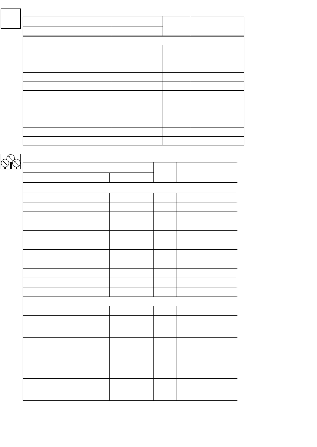
Table 17 Sensor data
Function
Read/
Write
Range
Imperial (metric)
Large Display Small Display
Page 1 of 2
Optional Sensor A Temperature TEMP A R 32-122°F (0-50°C)
Optional Sensor A Humidity HUM A R 20-80%
Optional Sensor B Temperature TEMP B R 32-122°F (0-50°C)
Optional Sensor B Humidity HUM B R 20-80%
Optional Sensor C Temperature TEMP C R 32-122°F (0-50°C)
Optional Sensor C Humidity HUM C R 20-80%
Freecooling Fluid Temperature FC TEMP R 4-113°F (-15 to 45°C)
Outdoor Temperature AMB TEMP R 4-113°F (-15 to 45°C)
Freecooling Status FC STATE R Off, Start, On, Blank
DigiScroll 1 Temperature DS1 TEMP R 84-313°F (29-156°C)
DigiScroll 2 Temperature DS2 TEMP R 84-313°F (29-156 °C)
Page 2 of 2
Daily High Temperature Hi Temp R 32-122°F (0-50°C)
Daily High Temperature
Hi Te H
Hi Te M
Hi Te S
R
-
Daily Low Temperature Lo Temp R 32-122°F (0-50°C)
Daily Low Temperature
Lo Te H
Lo Te M
Lo Te S
R
-
Daily High Humidity Hi Humi R 20-80%
Daily High Humidity
Hi Hu H
Hi Hu M
Hi Hu S
R
-
SET
ALARMS