
Intelligent Communications & Monitoring System User Manual
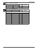
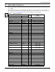
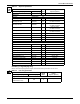
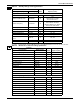
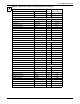
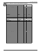
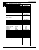
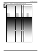
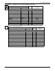
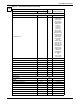
Table Of Contents
- 1.0 Introduction
- 2.0 Liebert iCOM Display Components and Functions
- Figure 2 Liebert iCOM display components
- Table 1 Keyboard icons and functions
- Figure 3 Status menu, large display, graphical view
- Figure 4 Liebert iCOM default screen symbols
- 2.1 Navigating Through the Liebert iCOM Menus
- 3.0 Operation
- 3.1 Single Unit Functions
- 3.2 Motorized Ball Valve in Digital Scroll Units
- 3.3 Temperature Control—Single Source Cooling (No Extra Cooling Coil)
- 3.3.1 Temperature Proportional Band
- 3.3.2 Compressor Control
- Compressor Proportional Bands
- Figure 12 One single-step compressor without unloaders
- Figure 13 Two single-step compressors without unloaders or one compressor with an unloader (two-step)
- Figure 14 Two compressors with unloaders (four-step)
- Figure 15 Digital scroll capacity modulation, 10-100% variable
- Figure 16 Single and dual digital scroll compressor activation points
- Compressor Proportional Bands
- 3.3.3 Chilled Water Control
- 3.4 Temperature Control—Second Cooling Source
- 3.5 Temperature Control—Reheat
- 3.6 Humidity Control
- 3.7 Control Types
- 3.8 Possible Event Notifications
- 3.9 Next Maintenance Calculation
- 4.0 Teamwork
- 5.0 Installing a Liebert iCOM Unit-to-Unit Network
- 5.1 Placement of Cooling Units
- 5.2 U2U Hardware: Cables and Network Switch
- 5.3 Wiring for Unit-to-Unit Communications—U2U
- 5.4 External Communications—Building Management Systems, Liebert SiteScan®
- 6.0 Mounting a Large Display on a Wall
- 7.0 User Menu Parameters
- 8.0 Service Menu Parameters
- Table 23 Setpoints parameters
- Unit Diary—Large Display Only
- Table 24 Unit diary parameters
- Table 25 Standby settings / lead-lag parameters
- Table 26 Maintenance / wellness settings parameters
- Table 27 Diagnostics / service mode parameters
- Table 28 Set alarms parameters
- Table 29 Sensor calibration / setup parameters
- Table 30 System / network setup parameters—large display only
- Table 31 Network setup parameters
- Table 32 Options setup parameters
- Table 33 Service contact info parameters
Service Menu Parameters
56
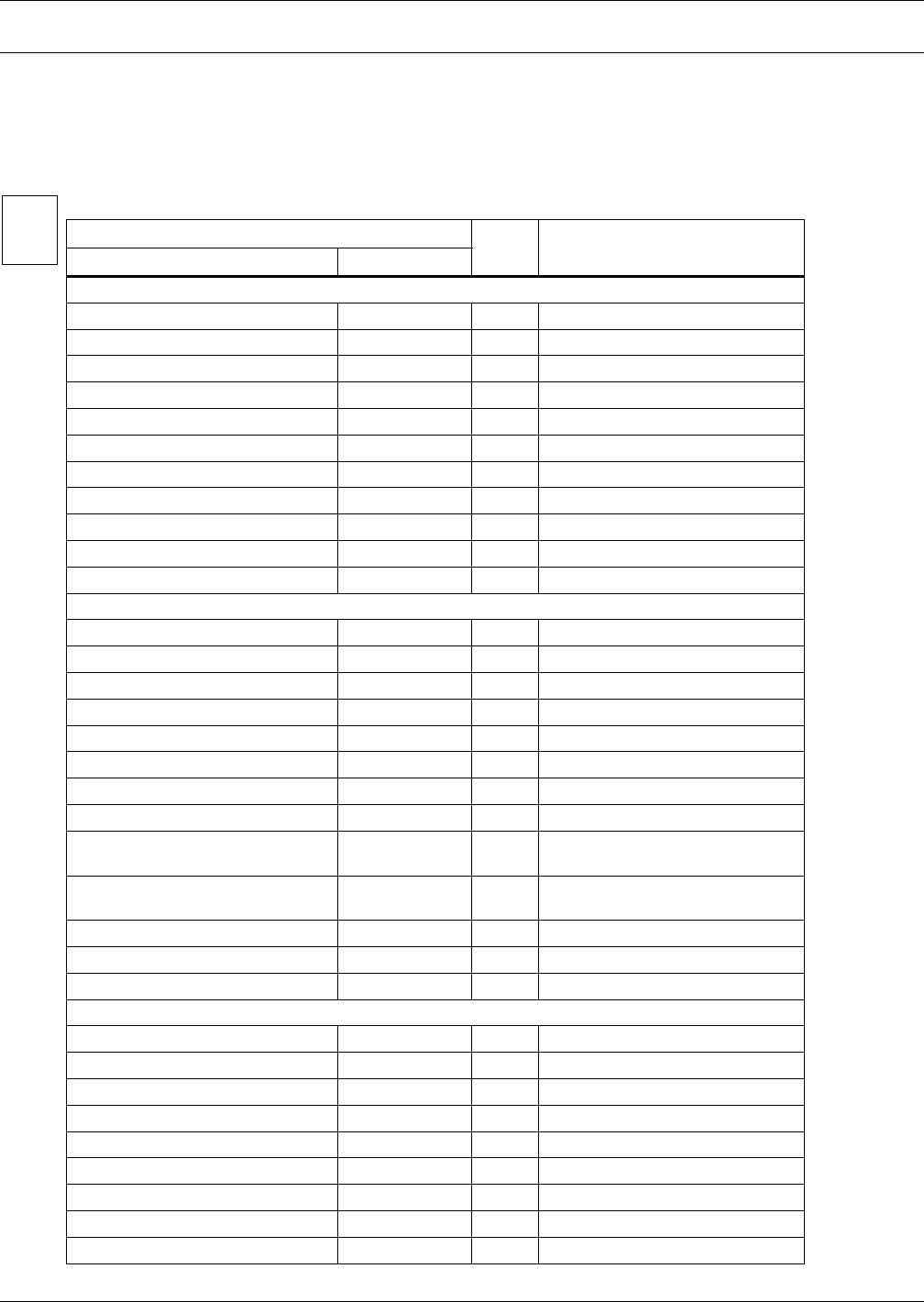
8.0 SERVICE MENU PARAMETERS
Service menus allow customized settings for site operations. The password for service menu parame-
ters is 5010.
The iCOM control firmware is being updated constantly. As a result, the Service menu parameter
tables shown in this manual may be slightly different than what is shown on your cooling unit's dis-
play. Please check www.liebert.com for the latest iCOM User manual updates.
Table 23 Setpoints parameters
Function
Read/
Write
Range
Imperial (metric)
Large Display Small Display
Page 1 of 5
Password PASSWORD W -
Temperature Setpoint TEMP SET W 41-104°F (5-40°C)
Control Type CTRL TYP W Proportional, PI, PID, Intelligent
Temperature Proportional Band TEMP PB W 2-54°F (1-30°C) autoset
Temperature Integration Time TEMP INT W 0-15 min, autoset
Temperature Derivative Time TEMP DER W 0-900 sec
AutoSet Enable AUTOSET W No, Yes
Temperature DeadBand TEMP DB W 0-36°F (0-20°C)
Second Setpoint 2ND SETP W 41-104°F (5-40°C)
Backup Temperature Setpoint BACK TSP W 41-104°F (5-40°C)
Page 2 of 5
Password PASSWORD W -
Humidity Setpoint HUM SET W 20-80%
Humidity Control Type HUM CTRL W Relative, Compensated, Predictive
Humidity Proportional Band HUM PB W 1-20%
Humidity Integration Time HUM INT W 0-15 min
Humidity Deadband HUM DB W 0-50%
Dehum/Heat Low Limit 1 LO LIM 1 W -9.9°F to -2.0°F
Dehum/Heat Low Limit 2 LO LIM 2 W -9.9°F to -2.0°F
internal variable Low Limit 1 reset
-10.0°F / -2.0°F
-5.5K / -1.1K
internal variable Low Limit 1 reset
-10.0°F / -2.0°F
-5.5K / -1.1K
Page 3 of 5
Password PASSWORD W -
Supply Limit SUP LIM W Enabled, Disabled
Supply Limit Temp Value SUP TEMP W 41-77°F (5-25°C)
DT between Room / FC Type FC TYPE W No, Contact, Value
DT between Room Air/ FC Fluid FC DT W 0-36°F (-18 - 2 °C)
Minimum CW Temp MIN CW W No, Yes
Minimum CW Temp Value MIN CW W 32-68°F (0-20°C)
VSD Fanspeed FANSPEED W Auto / Manual
°C / °F
% RH
SET