
Intelligent Communications & Monitoring System User Manual
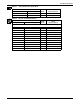
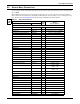
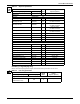
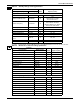
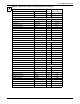
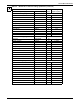
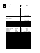
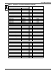
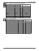
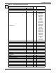
Table Of Contents
- 1.0 Introduction
- 2.0 Liebert iCOM Display Components and Functions
- Figure 2 Liebert iCOM display components
- Table 1 Keyboard icons and functions
- Figure 3 Status menu, large display, graphical view
- Figure 4 Liebert iCOM default screen symbols
- 2.1 Navigating Through the Liebert iCOM Menus
- 3.0 Operation
- 3.1 Single Unit Functions
- 3.2 Motorized Ball Valve in Digital Scroll Units
- 3.3 Temperature Control—Single Source Cooling (No Extra Cooling Coil)
- 3.3.1 Temperature Proportional Band
- 3.3.2 Compressor Control
- Compressor Proportional Bands
- Figure 12 One single-step compressor without unloaders
- Figure 13 Two single-step compressors without unloaders or one compressor with an unloader (two-step)
- Figure 14 Two compressors with unloaders (four-step)
- Figure 15 Digital scroll capacity modulation, 10-100% variable
- Figure 16 Single and dual digital scroll compressor activation points
- Compressor Proportional Bands
- 3.3.3 Chilled Water Control
- 3.4 Temperature Control—Second Cooling Source
- 3.5 Temperature Control—Reheat
- 3.6 Humidity Control
- 3.7 Control Types
- 3.8 Possible Event Notifications
- 3.9 Next Maintenance Calculation
- 4.0 Teamwork
- 5.0 Installing a Liebert iCOM Unit-to-Unit Network
- 5.1 Placement of Cooling Units
- 5.2 U2U Hardware: Cables and Network Switch
- 5.3 Wiring for Unit-to-Unit Communications—U2U
- 5.4 External Communications—Building Management Systems, Liebert SiteScan®
- 6.0 Mounting a Large Display on a Wall
- 7.0 User Menu Parameters
- 8.0 Service Menu Parameters
- Table 23 Setpoints parameters
- Unit Diary—Large Display Only
- Table 24 Unit diary parameters
- Table 25 Standby settings / lead-lag parameters
- Table 26 Maintenance / wellness settings parameters
- Table 27 Diagnostics / service mode parameters
- Table 28 Set alarms parameters
- Table 29 Sensor calibration / setup parameters
- Table 30 System / network setup parameters—large display only
- Table 31 Network setup parameters
- Table 32 Options setup parameters
- Table 33 Service contact info parameters
Service Menu Parameters
61
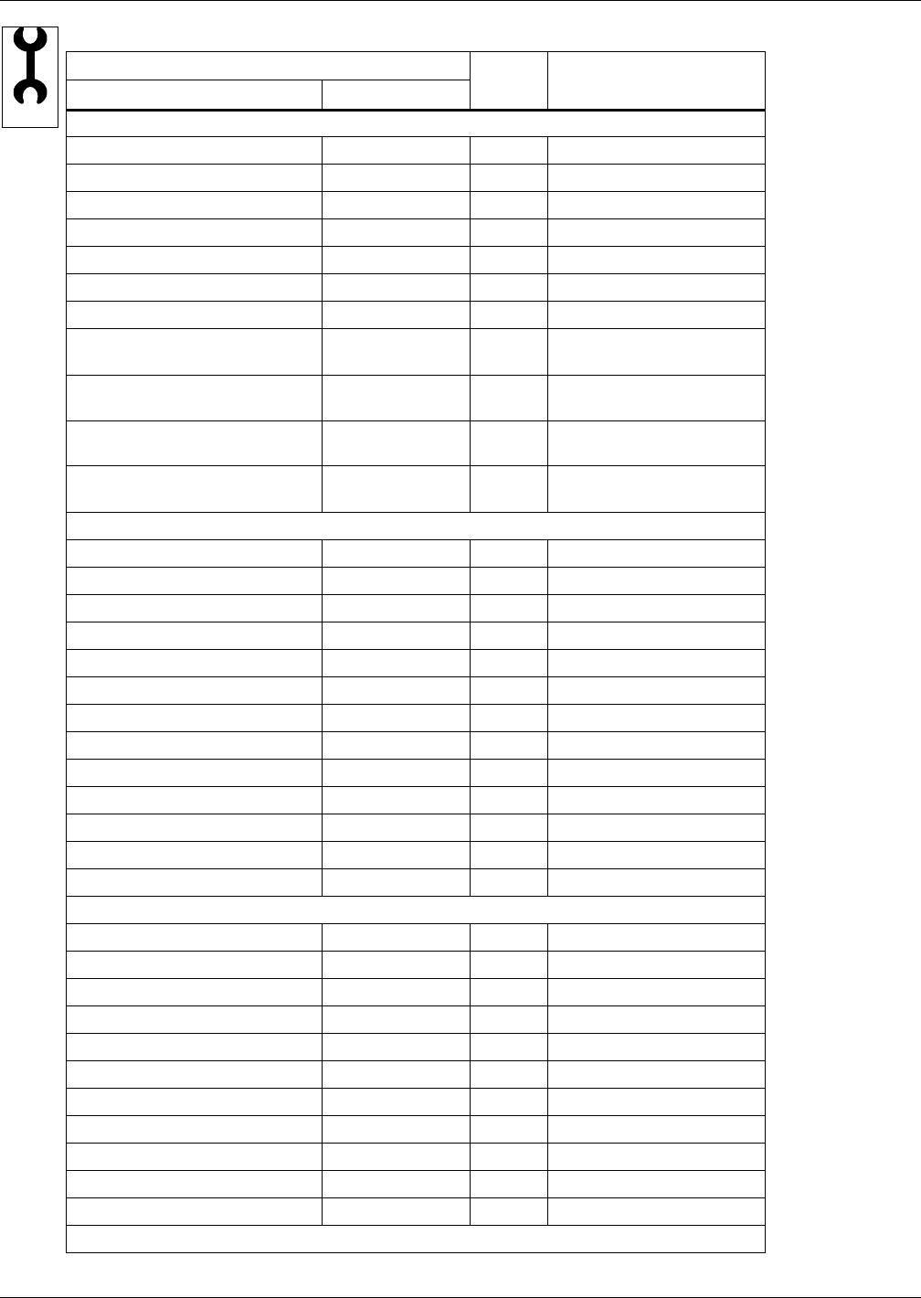
Table 27 Diagnostics / service mode parameters
Function
Read/
Write
Range
Imperial (metric)
Large Display Small Display
Page 1 of 7
Password PASSWORD W -
HP 1 Alarm Code HP1 CODE W 0-999
HP 2 Alarm Code HP2 CODE W 0-999
HT 1 Alarm Counter HT1 CNT W 0-999
HT 2 Alarm Counter HT2 CNT W 0-999
LP 1 Alarm Code LP 1 CODE W 0-999
LP 2 Alarm Code LP2 CODE W 0-999
Actual LP1 Pressure
LP1 ACT R - 145.0 - 725.0 psi
(-10.0 to 50.0 bar)
Actual LP2 Pressure
LP2 ACT R - 145.0 - 725.0 psi
(-10.0 to 50.0 bar)
Actual HP1 Pressure
HP1 ACT R - 145.0 - 725.0 psi
(-10.0 to 50.0 bar)
Actual HP2 Pressure
HP2 ACT R - 145.0 - 725.0 psi
(-10.0 to 50.0 bar)
Page 2 of 7
Password PASSWORD W -
Manual Mode MANUAL W No, Yes
Motor(s) MOTOR(S) W Off, On
Compressor 1 COMP1 W Off, On
Compressor 1 C1 MODE W Run, Evacuate, Charge
Compressor 1 Capacity C1 CAP W Off, On
Compressor 1 Cycle Ramp C1 CYCLE W 0-100%
Compressor 1 LLSV LLSV 1 W Off, On
Compressor 2 COMP2 W Off, On
Compressor 2 C2 MODE W Run, Evacuate, Charge
Compressor 2 Capacity C2 CAP W Off, On
Compressor 2 Cycle Ramp C2 CYCLE W 0-100%
Compressor 2 LLSV LLSV 2 W Off, On
Page 3 of 7
Password PASSWORD W -
Electric Heat 1 (or HG/HW) EL HEAT1 W Off, On
Electric Heat 2 (or E.Heat 1) EL HEAT2 W Off, On
Electric Heat 3 (or E.Heat 2) EL HEAT3 W Off, On
SCR Heat SCR HEAT W 0-100%
Dehumidification Output DEHUM W Off, On
Humidfier Fill HUM FILL W Off, On
Humidifier HUM W Off, On
Humidfier Drain H DRAIN W Off, On
Humidifier Current HUM.C. R 0.00 - 99.99A
Page 4 of 7
SERVICE