
Intelligent Communications & Monitoring System User Manual

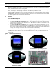
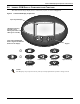
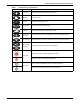
Table Of Contents
- 1.0 Introduction
- 2.0 Liebert iCOM Display Components and Functions
- Figure 2 Liebert iCOM display components
- Table 1 Keyboard icons and functions
- Figure 3 Status menu, large display, graphical view
- Figure 4 Liebert iCOM default screen symbols
- 2.1 Navigating Through the Liebert iCOM Menus
- 3.0 Operation
- 3.1 Single Unit Functions
- 3.2 Motorized Ball Valve in Digital Scroll Units
- 3.3 Temperature Control—Single Source Cooling (No Extra Cooling Coil)
- 3.3.1 Temperature Proportional Band
- 3.3.2 Compressor Control
- Compressor Proportional Bands
- Figure 12 One single-step compressor without unloaders
- Figure 13 Two single-step compressors without unloaders or one compressor with an unloader (two-step)
- Figure 14 Two compressors with unloaders (four-step)
- Figure 15 Digital scroll capacity modulation, 10-100% variable
- Figure 16 Single and dual digital scroll compressor activation points
- Compressor Proportional Bands
- 3.3.3 Chilled Water Control
- 3.4 Temperature Control—Second Cooling Source
- 3.5 Temperature Control—Reheat
- 3.6 Humidity Control
- 3.7 Control Types
- 3.8 Possible Event Notifications
- 3.9 Next Maintenance Calculation
- 4.0 Teamwork
- 5.0 Installing a Liebert iCOM Unit-to-Unit Network
- 5.1 Placement of Cooling Units
- 5.2 U2U Hardware: Cables and Network Switch
- 5.3 Wiring for Unit-to-Unit Communications—U2U
- 5.4 External Communications—Building Management Systems, Liebert SiteScan®
- 6.0 Mounting a Large Display on a Wall
- 7.0 User Menu Parameters
- 8.0 Service Menu Parameters
- Table 23 Setpoints parameters
- Unit Diary—Large Display Only
- Table 24 Unit diary parameters
- Table 25 Standby settings / lead-lag parameters
- Table 26 Maintenance / wellness settings parameters
- Table 27 Diagnostics / service mode parameters
- Table 28 Set alarms parameters
- Table 29 Sensor calibration / setup parameters
- Table 30 System / network setup parameters—large display only
- Table 31 Network setup parameters
- Table 32 Options setup parameters
- Table 33 Service contact info parameters
Introduction
1
1.0 INTRODUCTION
The Liebert iCOM
™
control offers the highest capabilities in unit control, communication and moni-
toring of Liebert mission-critical cooling units.
Liebert iCOM may be used to combine multiple cooling units into a team that operates as a single
entity, enhancing the already-high performance and efficiency of Liebert’s units.
Liebert iCOM is available as a factory-installed assembly or may be retrofitted on existing products
with SM, AM or AG controls. Large graphic display wall-mount versions of the control are available
for remote operation and monitoring of cooling units.
1.1 Features
Large and Small Displays
The Liebert iCOM control is available with either a large or small liquid crystal display.
•The Liebert iCOM with small display has a 128 x 64 dot matrix screen that simultaneously
shows two menu icons, along with descriptive text. This display is capable of controlling only the
unit it is directly connected to.
•The Liebert iCOM with large display has a 320 x 240 dot matrix screen that shows up to 16
menu icons at a time, as well as descriptive text. This display can be used to control a single cool-
ing unit or any cooling unit on a network, regardless of how it is connected—either integrated into
a cooling unit or simply connected to the network and mounted remotely.
Liebert iCOM’s menu-driven display is used for all programming functions on each connected cooling
unit. The Status menu shows the status of the conditioned space, such as room temperature and
humidity, temperature and humidity setpoints, alarm status and settings, event histories and the
current time.
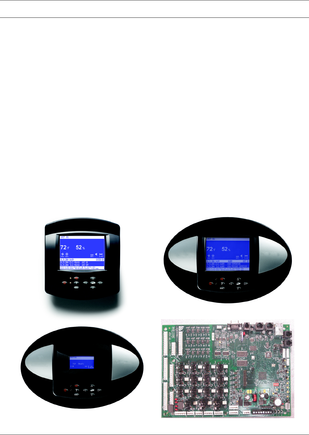
Figure 1 Liebert iCOM components
Wall Mount Large Display
Direct Panel Mount
Small Display and Bezel
Direct Panel Mount Large Display and Bezel
Liebert iCOM Input/Output Board