
Intelligent Communications & Monitoring System User Manual
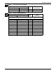
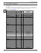
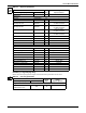
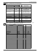
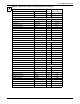
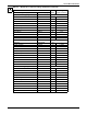
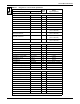
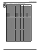
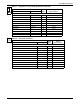
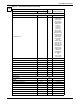
Table Of Contents
- 1.0 Introduction
- 2.0 Liebert iCOM Display Components and Functions
- Figure 2 Liebert iCOM display components
- Table 1 Keyboard icons and functions
- Figure 3 Status menu, large display, graphical view
- Figure 4 Liebert iCOM default screen symbols
- 2.1 Navigating Through the Liebert iCOM Menus
- 3.0 Operation
- 3.1 Single Unit Functions
- 3.2 Motorized Ball Valve in Digital Scroll Units
- 3.3 Temperature Control—Single Source Cooling (No Extra Cooling Coil)
- 3.3.1 Temperature Proportional Band
- 3.3.2 Compressor Control
- Compressor Proportional Bands
- Figure 12 One single-step compressor without unloaders
- Figure 13 Two single-step compressors without unloaders or one compressor with an unloader (two-step)
- Figure 14 Two compressors with unloaders (four-step)
- Figure 15 Digital scroll capacity modulation, 10-100% variable
- Figure 16 Single and dual digital scroll compressor activation points
- Compressor Proportional Bands
- 3.3.3 Chilled Water Control
- 3.4 Temperature Control—Second Cooling Source
- 3.5 Temperature Control—Reheat
- 3.6 Humidity Control
- 3.7 Control Types
- 3.8 Possible Event Notifications
- 3.9 Next Maintenance Calculation
- 4.0 Teamwork
- 5.0 Installing a Liebert iCOM Unit-to-Unit Network
- 5.1 Placement of Cooling Units
- 5.2 U2U Hardware: Cables and Network Switch
- 5.3 Wiring for Unit-to-Unit Communications—U2U
- 5.4 External Communications—Building Management Systems, Liebert SiteScan®
- 6.0 Mounting a Large Display on a Wall
- 7.0 User Menu Parameters
- 8.0 Service Menu Parameters
- Table 23 Setpoints parameters
- Unit Diary—Large Display Only
- Table 24 Unit diary parameters
- Table 25 Standby settings / lead-lag parameters
- Table 26 Maintenance / wellness settings parameters
- Table 27 Diagnostics / service mode parameters
- Table 28 Set alarms parameters
- Table 29 Sensor calibration / setup parameters
- Table 30 System / network setup parameters—large display only
- Table 31 Network setup parameters
- Table 32 Options setup parameters
- Table 33 Service contact info parameters

Service Menu Parameters
64
Page 2 of 7
Password PASSWORD W -
Customer Input 1
CUST IN1 W Smoke
Water Alarm
C PMP Alarm
Flow Alarm
Stdby G Pmp
Stdby Unit
C-Input 1
C-Input 2
C-Input 3
C-Input 4
Rht Lockout
Hum Lockout
Rht+Hum Lock
Comp Lockout
Call Service
High Temp
FC Lockout
Air Loss
Heater Alarm
Flow AL SD
Flow AL LC
Comp Lock PD
Enable FC
HTRJ VFD
HTRJ TVSS
Fire Alarm,
2nd Setpoint,
No Power,
LSI,
Cond 1 Fail,
Cond 2 Fail
Customer Input 1 active when C2 ACT W Open, Closed
Customer Input 2 CUST IN2 W Like Custom 2
Customer Input 2 active when C2 ACT W Closed, Open
Customer Input 3 CUST IN3 W Like Custom 2
Customer Input 3 active when C3 ACT W Closed, Open
Customer Input 4 CUST IN4 W Like Custom 2
Customer Input 4 active when C4 ACT W Closed, Open
WARNING ACTIVATES ALARM RELAY WA AC AL W No, Yes
Reset Disabled Alarms AL.RES. W No, Yes
Page 3 of 7
PASSWORD - W -
DELAY -- -
MAIN FAN OVERLOAD FOL W 0 - 9999 sec
LOSS OF AIRFLOW LOA W 0 - 9999 sec
CLOGGED FILTERS CF W 0 - 9999 sec
HIGH ROOM TEMP HRT W 0 - 9999 sec
LOW ROOM TEMP LRT W 0 - 9999 sec
HIGH ROOM HUM HRH W 0 - 9999 sec
LOW ROOM HUM LRH W 0 - 9999 sec
Table 28 Set alarms parameters (continued)
Function
Read/
Write
Range
Imperial (metric)
Large Display Small Display
SET
ALARMS