
Intelligent Communications & Monitoring System User Manual
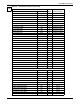


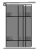
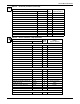
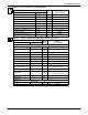
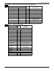
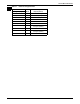
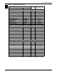
Table Of Contents
- 1.0 Introduction
- 2.0 Liebert iCOM Display Components and Functions
- Figure 2 Liebert iCOM display components
- Table 1 Keyboard icons and functions
- Figure 3 Status menu, large display, graphical view
- Figure 4 Liebert iCOM default screen symbols
- 2.1 Navigating Through the Liebert iCOM Menus
- 3.0 Operation
- 3.1 Single Unit Functions
- 3.2 Motorized Ball Valve in Digital Scroll Units
- 3.3 Temperature Control—Single Source Cooling (No Extra Cooling Coil)
- 3.3.1 Temperature Proportional Band
- 3.3.2 Compressor Control
- Compressor Proportional Bands
- Figure 12 One single-step compressor without unloaders
- Figure 13 Two single-step compressors without unloaders or one compressor with an unloader (two-step)
- Figure 14 Two compressors with unloaders (four-step)
- Figure 15 Digital scroll capacity modulation, 10-100% variable
- Figure 16 Single and dual digital scroll compressor activation points
- Compressor Proportional Bands
- 3.3.3 Chilled Water Control
- 3.4 Temperature Control—Second Cooling Source
- 3.5 Temperature Control—Reheat
- 3.6 Humidity Control
- 3.7 Control Types
- 3.8 Possible Event Notifications
- 3.9 Next Maintenance Calculation
- 4.0 Teamwork
- 5.0 Installing a Liebert iCOM Unit-to-Unit Network
- 5.1 Placement of Cooling Units
- 5.2 U2U Hardware: Cables and Network Switch
- 5.3 Wiring for Unit-to-Unit Communications—U2U
- 5.4 External Communications—Building Management Systems, Liebert SiteScan®
- 6.0 Mounting a Large Display on a Wall
- 7.0 User Menu Parameters
- 8.0 Service Menu Parameters
- Table 23 Setpoints parameters
- Unit Diary—Large Display Only
- Table 24 Unit diary parameters
- Table 25 Standby settings / lead-lag parameters
- Table 26 Maintenance / wellness settings parameters
- Table 27 Diagnostics / service mode parameters
- Table 28 Set alarms parameters
- Table 29 Sensor calibration / setup parameters
- Table 30 System / network setup parameters—large display only
- Table 31 Network setup parameters
- Table 32 Options setup parameters
- Table 33 Service contact info parameters

Service Menu Parameters
68
REHEAT LOCKOUT RL W Disabled, Enabled
HUMIDIFIER LOCKOUT HL W Disabled, Enabled
FC LOCKOUT FCL W Disabled, Enabled
COMPRESSOR(S) LOCKOUT CL W Disabled, Enabled
TYPE -- -
CUSTOMER INPUT 1 CI1 W MSG, WRN, ALM
CUSTOMER INPUT 2 CI2 W MSG, WRN, ALM
CUSTOMER INPUT 3 CI3 W MSG, WRN, ALM
CUSTOMER INPUT 4 CI4 W MSG, WRN, ALM
CALL SERVICE CS W MSG, WRN, ALM
HIGH TEMPERATURE HTD W MSG, WRN, ALM
LOSS OF AIR BLOWER 1 LB1 W MSG, WRN, ALM
REHEAT LOCKOUT RL W MSG, WRN, ALM
HUMIDIFIER LOCKOUT HL W MSG, WRN, ALM
FC LOCKOUT FCL W MSG, WRN, ALM
COMPRESSOR(S) LOCKOUT CL W MSG, WRN, ALM
Page 7 of 7
PASSWORD -W -
DELAY -- -
COMP 1 SHORT CYCLE SC1 W 0 - 9999 sec
COMP 2 SHORT CYCLE SC2 W 0 - 9999 sec
NO POWER NOP W 0 - 9999 sec
CONDENSER 1 FAILURE CN1 W 0 - 9999 sec
CONDENSER 2 FAILURE CN2 W 0 - 9999 sec
----
----
----
----
----
----
ENABLE - DISAB - - -
COMP 1 SHORT CYCLE SC1 W Disabled, Enabled
COMP 2 SHORT CYCLE SC2 W Disabled, Enabled
NO POWER NOP W Disabled, Enabled
CONDENSER 1 FAILURE CN1 W Disabled, Enabled
CONDENSER 2 FAILURE CN2 W Disabled, Enabled
----
----
----
----
----
----
Table 28 Set alarms parameters (continued)
Function
Read/
Write
Range
Imperial (metric)
Large Display Small Display
SET
ALARMS