
Intelligent Communications & Monitoring System User Manual
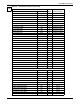


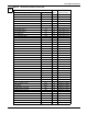
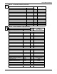
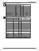
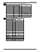
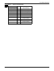
Table Of Contents
- 1.0 Introduction
- 2.0 Liebert iCOM Display Components and Functions
- Figure 2 Liebert iCOM display components
- Table 1 Keyboard icons and functions
- Figure 3 Status menu, large display, graphical view
- Figure 4 Liebert iCOM default screen symbols
- 2.1 Navigating Through the Liebert iCOM Menus
- 3.0 Operation
- 3.1 Single Unit Functions
- 3.2 Motorized Ball Valve in Digital Scroll Units
- 3.3 Temperature Control—Single Source Cooling (No Extra Cooling Coil)
- 3.3.1 Temperature Proportional Band
- 3.3.2 Compressor Control
- Compressor Proportional Bands
- Figure 12 One single-step compressor without unloaders
- Figure 13 Two single-step compressors without unloaders or one compressor with an unloader (two-step)
- Figure 14 Two compressors with unloaders (four-step)
- Figure 15 Digital scroll capacity modulation, 10-100% variable
- Figure 16 Single and dual digital scroll compressor activation points
- Compressor Proportional Bands
- 3.3.3 Chilled Water Control
- 3.4 Temperature Control—Second Cooling Source
- 3.5 Temperature Control—Reheat
- 3.6 Humidity Control
- 3.7 Control Types
- 3.8 Possible Event Notifications
- 3.9 Next Maintenance Calculation
- 4.0 Teamwork
- 5.0 Installing a Liebert iCOM Unit-to-Unit Network
- 5.1 Placement of Cooling Units
- 5.2 U2U Hardware: Cables and Network Switch
- 5.3 Wiring for Unit-to-Unit Communications—U2U
- 5.4 External Communications—Building Management Systems, Liebert SiteScan®
- 6.0 Mounting a Large Display on a Wall
- 7.0 User Menu Parameters
- 8.0 Service Menu Parameters
- Table 23 Setpoints parameters
- Unit Diary—Large Display Only
- Table 24 Unit diary parameters
- Table 25 Standby settings / lead-lag parameters
- Table 26 Maintenance / wellness settings parameters
- Table 27 Diagnostics / service mode parameters
- Table 28 Set alarms parameters
- Table 29 Sensor calibration / setup parameters
- Table 30 System / network setup parameters—large display only
- Table 31 Network setup parameters
- Table 32 Options setup parameters
- Table 33 Service contact info parameters
Service Menu Parameters
73
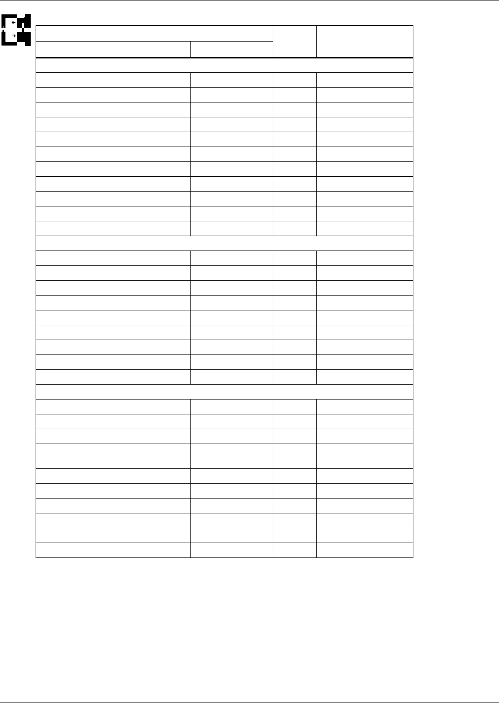
Table 32 Options setup parameters
Function
Read/
Write
Range
Imperial (metric)
Large Display Small Display
Page 1 of 3
Password PASSWORD W -
Compressor Sequence COMP SEQ R Auto, 1, 2
Low Pressure Alarm Delay LP DELAY W 0-5 min
Electric Stages EL HEAT W 0, 1, 2, 3
Hot Water Heat On/Off HW HEAT W No, Yes
Total Heat Stages ALL HEAT R 0, 1, 2, 3
LWD Connected LWDconn W No, Yes
3P Actuator Runtime 3P RUN W 30-500 sec
3P Actuator Direction 3P DIR W Direct, Reverse
Page 2 of 3
Password PASSWORD W -
Humidification Enabled HUM ENAB W No, Yes
Infrared Flush Rate IR FLUSH W 110-500%
Humidifier Steam Rate HUM STEAM W No, Yes
Humidifier Bottle Flush Time HumFlush W 5-30 sec
Humidifier Bottle Manual Flush ManFlush V Yes, No
Auto Restart Enabled REST EN W Yes, No
Single Unit Auto Restart RESTART W 0-999 sec
On-Off Enabled ONOFF EN W Yes, No
Page 3 of 3
CW Flush CW FLUSH W 0-99 hours
Freecooling Flush FC FLUSH W 0-99 hours
Hot Water Flush HW FLUSH W 0-99 hours
Ball Valve Setpoint Offset BALL OFF W
-1.8 / 3.5 bar
(-26 / +51 psi)