
User manual


Installing a Liebert iCOM Unit-to-Unit Network
36
5.3.1 Wiring a Liebert iCOM U2U Network
Small Displays
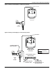
Two cooling units, each with a small display: To network two cooling units, each with a small display,
connect a crossover CAT5e cable between the P64 connectors on each cooling unit’s Liebert iCOM
input/output board. A network switch is not needed (see Figure 18).
Figure 18 Connecting two cooling units, each with a small display using a crossover Ethernet cable
Three or more units with small displays: To network three or more cooling units, each equipped with
a small display, connect a straight-through CAT5e Ethernet cable from the P64 connector on each
cooling unit’s Liebert iCOM input/output board to a common network switch (see Figure 20).
Large Displays
A network switch is required to enable Ethernet communication on one or more cooling units with
large displays. Each cooling unit with a large display requires two straight-through Ethernet cables
from a network switch. One cable connects to port P64 on the Liebert iCOM input/output board and
the other cable connects to port P64 on the back of the large display (see Figure 22).
Wall-Mount Large Display
Only large displays can be used for remotely monitoring and controlling cooling units connected on
the same network. Each wall-mount large display requires 230V (120V) input power; Emerson pro-
vides an AC adapter wall plug. A straight-through Ethernet cable must be connected between the net-
work switch and the P64 port on the back of the display. This will enable control and monitoring
capabilities to any cooling unit connected to the network. See 6.0 - Mounting a Large Display on a
Wall for mounting details and Figure 25 for wall-mount dimensions.
Combining Large and Small Displays on a U2U Network
Setting up a network of cooling units equipped with large and small displays requires a network
switch. The controls are to be connected to the switch as described above.