
User's Manual


User Menu Parameters
Liebert
®
iCOM
®
110
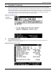
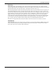
U305 FC Status / Amb Temp—Displays the operating status of air side economizer (left hand value)
and displays the current outside air temperature (right hand value). The operating status values
include: Off, Start and On.
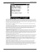
U305 Freecooling Status—Displays the operating status of free cool or dual cool economizer (left
hand value) and displays the current outside air temperature (right hand value). The operating
status values include: Off, Start and On.
U306 CW Temp In / Out—Displays the calibrated chilled water inlet (left hand value) and outlet
(right hand value) temperature. If two chilled water inlet/outlet sensors are connected, the
description will change to 'CW Temp C1 In / Out.'
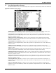
U307 CW Flow Circuit 1—Displays the calibrated fluid flow through the unit in gallons per minute
or liters per minute. The description show will change depending on the unit type installed. Single
Circuit chilled water units will read 'CW Flow', Dual Chilled water circuit units will read 'CW Flow
Circuit 1', Free cooling or dual cool unit will display 'FC Fluid Flow' and DX units with water/glycol
cooled heat exchangers will read “Glycol Flow.”
U308 CW Temp C2 In / Out—Displays the calibrated chilled water inlet (left hand value) and outlet
(right hand value) temperature of the second circuit on a dual chilled water unit.
U309 CW Flow Circuit 2—Displays the calibrated fluid flow through the unit in gallons per minute
or liters per minute.
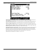
U310 Total Cooling Load kW—Displays the calculated chilled water cooling load based on the
temperature difference from supply to return and the fluid flow rate. If the display is set to read
KBtuH, the line description will update to “Total Cooling Load KBtuH.”
U311 Static Pressure inWC / Pa—Displays the calibrated static pressure in inWC (left hand value)
and Pa (right hand value).
U312 SYS Static Pressure inWC / Pa—Displays the calibrated static pressure inWC (left hand
value) and Pa (right hand value) where multiple static pressure sensor are shared across the iCOM
U2U network. The reading displayed will be an average or minimum pressure of all connected units
based on S197 SP Teamwork / Network mode setting.
U31A Calculated Airflow—Shows the calculated airflow based on an installed differential pressure
transducer.