
User's Manual


Operation
Liebert
®
iCOM
®
18
3.0 OPERATION
The Liebert iCOM display provides viewing, trending and configuration capability for Liebert cooling
units. All unit settings and parameters can be viewed and adjusted through three menus: User,
Service and Advanced. All active alarms are displayed on the LCD and annunciated.
The control is shipped from the factory with default selections for all necessary settings. Adjustments
can be made if the defaults do not meet your requirements.
References to menu items in this manual are followed by the main menu and the submenu where they
can be found.
For example:
• Temperature Setpoint (User Menu, Setpoints) - The Temperature Setpoint parameter is
located in the User menu under the Setpoints submenu.
• High Return Humidity (Service Menu, Set Alarms) - The High Return Humidity alarm is
located in the Service menu under the Set Alarms submenu.
3.1 Single Unit Functions
3.1.1 Unit/Fan Control
Start - Stop
The unit may be switched On and Off by pressing the On/Off button, through a remote device or by
internal safety device(s). In all cases, the fan output is first activated when the unit is switched On
and will remain On as long as the unit is running. Each time a unit is turned On or Off, the unit
status is updated to reflect the current operating mode and an event is added to the Event Log. Unit
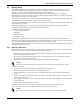
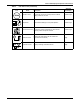
statuses displayed include:
• ALARM OFF—The unit has an alarm that has forced the unit to turn Off.
• MANUAL—Unit is being controlled by a service technician using the Service Diagnostics Manual
Mode.
• LOCAL OFF—When a unit is turned Off from the Unit Status Screen or small display,
LOCAL OFF is shown for unit status.
• DISPLAY OFF—When a unit is turned Off from the System Screen of a large display, Display
OFF is shown for unit status.
• ALARM STANDBY—The unit has been rotated into standby because an active alarm on the unit
is present.
• STANDBY—The unit is in standby based on the Lead / Lag settings in the Service Menu.
• TIMER OFF—The unit has been set to Sleep and is waiting for the next start interval. See
User / Sleep Mode Menu.
• UNIT ON—The unit is operating normally without alarm or warning.
• WARNING ON—The unit has an active warning but is still operating. See User / Active alarms
for details.
• ALARM ON—The unit has an active alarm but is still operating. See User / Active alarms for
details.
• TIMER—The unit is configured on a timer to only operate at certain times. See User / Sleep Mode
Menu.
• REMOTE OFF—Remote shutdown terminals will turn Off the connected unit and the front
display shows REMOTE OFF as the status. This command is invoked when a normally closed set
of dry contacts opens. The remote On/Off and display On/Off switches are in series. A cooling unit
will start only if both switches are On. If one of these switches is Off, the unit will stop. See
Figure 18 for more information.
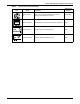
• MONITORNG OFF—In this case, an override to the monitoring is possible: Pressing the On-Off
button of the display will change the state to Unit Off; pressing again may start the unit in Unit
On. If the unit does not turn On, check the remote monitoring device or call 800-543-2778 for
assistance.
• BACK-DRAFT—The unit is in a non-operational mode, but is operating the EC fan as a
back-draft damper.