
User's Manual


Teamwork
Liebert
®
iCOM
®
84
4.3.1 Tools Required for Installation
• Small, non-conductive tool for setting control DIP switches
• Medium flat-head screw driver for opening electric panel protective dead-front.
• Cutting tool to trim cable ties
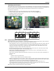
• Small Phillips-head screwdriver to open 2T housing
4.3.2 DIP Switch Settings
The individual 2T sensor must be given a unique address on the CANbus cable run to the associated
Liebert unit. DIP switches are used to give the 2T sensor its unique address. It is important to
confirm that the DIP switches have been set correctly using Table 17. Although it is not required, it
is recommended that the DIP switch sensor number settings correspond to the number of 2T sensors
on the CANbus run. For example, if there are only four 2T sensors used for a particular Liebert CW
unit then the individual DIP switch settings should correspond to address #1, #2, #3 and #4. If the
DIP switches are not set correctly, the control will not operate properly.
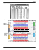
Figure 70 DIP switches in 2T sensors
Table 17 DIP switch settings for remote sensor applications
2T Sensor #
DIP switch Position
12345678
1 Off Off On Off On Off Off Off
2 On Off On Off On Off Off Off
3 Off On On Off On Off Off Off
4 On On On Off On Off Off Off
5 Off Off Off On On Off Off Off
6 On Off Off On On Off Off Off
7 Off On Off On On Off Off Off
8 On On Off On On Off Off Off
9 Off Off On On On Off Off Off
10 On Off On On On Off Off Off
Switch Up = ON
Switch Down = OFF