Precision Cooling For Business-Critical Continuity™ Liebert® MC™ User Manual, 60Hz Air-Cooled Microchannel Condensers
TABLE OF CONTENTS IMPORTANT SAFETY GUIDELINES . . . . . . . . . . . . . . . . . . . . . . . . . . . . . . . . . . . . . . . . . . . . . . . . . .1 LIEBERT MC NOMENCLATURE . . . . . . . . . . . . . . . . . . . . . . . . . . . . . . . . . . . . . . . . . . . . . . . . . . . .3 1.0 INTRODUCTION . . . . . . . . . . . . . . . . . . . . . . . . . . . . . . . . . . . . . . . . . . . . . . . . . . . . . . . . . .4 1.1 Control/Fan Types . . . . . . . . . . . . . . . . . . . . . . . . . . . . . . . . . . . . . . .
6.0 CHECKLIST FOR COMPLETED INSTALLATION . . . . . . . . . . . . . . . . . . . . . . . . . . . . . . . . . . . 40 6.1 Moving and Placing Equipment . . . . . . . . . . . . . . . . . . . . . . . . . . . . . . . . . . . . . . . . . . . . . . . 40 6.2 Electrical . . . . . . . . . . . . . . . . . . . . . . . . . . . . . . . . . . . . . . . . . . . . . . . . . . . . . . . . . . . . . . . . . 40 6.3 Piping . . . . . . . . . . . . . . . . . . . . . . . . . . . . . . . . . . . . . . . . . . . . . . . . . . .
FIGURES Figure 1 Figure 2 Figure 3 Figure 4 Figure 5 Figure 6 Figure 7 Figure 8 Figure 9 Figure 10 Figure 11 Figure 12 Figure 13 Figure 14 Figure 15 Figure 16 Figure 17 Figure 18 Figure 19 Figure 20 Figure 21 Figure 22 Figure 23 Figure 24 Figure 25 Figure 26 Figure 27 Figure 28 Figure 29 Figure 30 Figure 31 Figure 32 Figure 33 Two-fan Liebert MC condenser . . . . . . . . . . . . . . . . . . . . . . . . . . . . . . . . . . . . . . . . . . . . . . . . . . . . . 4 Typical footprint dimensions, all units . . .
TABLES Table 1 Table 2 Table 3 Table 4 Table 5 Table 6 Table 7 Table 8 Table 9 Table 10 Table 11 Table 12 Table 13 Table 14 Table 15 Table 16 Table 17 Table 18 Table 19 Condenser net weights, shipping weights, dimensions and volume, approximate . . . . . . . . . . . . . 6 Condenser net weight addition—taller legs . . . . . . . . . . . . . . . . . . . . . . . . . . . . . . . . . . . . . . . . . . . 6 Condenser leg height and additional weight, MCL055, MCL110, MCL165 and MCK220. . . . . .
Important Safety Guidelines IMPORTANT SAFETY GUIDELINES SAVE THESE INSTRUCTIONS This manual contains important safety instructions that should be followed during the installation and maintenance of the Liebert MC. Read this manual thoroughly before attempting to install or operate this unit. Only qualified personnel should move, install or service this equipment. Adhere to all warnings, cautions and installation, operating and safety instructions on the unit and in this manual.
Important Safety Guidelines ! CAUTION Risk of sharp edges, splinters and exposed fasteners. Can cause personal injury. Only properly trained and qualified personnel wearing appropriate safety headgear, gloves, shoes, and glasses should attempt to move, lift, remove packaging from or prepare unit for installation. ! CAUTION Risk of explosive discharge of high-pressure gas. Can cause injury.
Liebert MC Nomenclature LIEBERT MC NOMENCLATURE Model Number – Part 1/2 Model Details Part 2/2 1 2 3 4 5 6 7 8 9 10 11 12 13 14 15 16 17 18 19 20 21 22 23 24 25 M C M 0 4 0 E 1 A D 0 A 0 V U 0 0 0 0 0 0 * * * * 1-2. Unit Family; MC = Microchannel Condenser 12. Panel Material 3. Platform Size A = Bright Aluminum S = Small 13. Connection Pipe Unit of Measurement M = Medium 0 = Inches (Std. ACR Copper) L = Large 14. Legs Included 4-6.
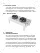
Introduction 1.0 INTRODUCTION 1.1 Product Description and Features The Liebert MC condenser is a low-profile, direct-drive propeller fan-type air-cooled unit suitable for mounting outdoors. It provides heat rejection for either one or two separate refrigeration circuits, matches the heat rejection capacity corresponding with the outdoor ambient temperature, and with each corresponding compressor heat rejection requirements.
Introduction 1.1.2 Liebert Lee-Temp™ Refrigerant Control The Liebert Lee-Temp head pressure control system utilizes head pressure control valve(s), extra refrigerant and insulated refrigerant receiver(s) with heater pads to assist system starting and to maintain proper operating head pressures in outdoor ambient temperatures below the rating point of the Liebert MC control type.
Site Preparation 2.0 SITE PREPARATION 2.1 Site Considerations • Condensers should be installed in a location offering maximum security and access for maintenance. • Avoid ground-level sites with public access and areas prone to heavy snow or ice accumulations. • To ensure adequate air supply, Emerson® recommends that condensers be installed in an area with clean air, away from loose dirt and foreign matter that might clog the coil.
Site Preparation Figure 2 Typical footprint dimensions, all units 13/16" (21mm) 3-5/8" (93mm) 2-1/2" (64mm) 1-7/8" (48mm) 2-1/2" (64mm) 1/2"x1" (12.7mm x 25.4mm) Obround 3-5/8" (93mm) 1-7/8" (48mm) Figure 3 Condenser planning dimensional data—MCS028 51-5/8" (1310mm) 42-3/4" (1085mm) 51-5/8" (1310mm) 42-3/4" (1085mm) Height to Top of Fan Guard C B B A Emerson recommends a clearance of 36" (915mm) on each side for proper operation and component access.
Site Preparation Condenser planning dimensions—MCM040, MCM080, MCM160 with/without Liebert Lee-Temp™ Figure 4 46-1/4" (1175mm) Emerson recommends a clearance of 36" (915mm) on each side for proper operation and component access.
Site Preparation Figure 5 Condenser planning dimensions–MCM120 Emerson recommends a clearance of 36" (915mm) on each end and each side for proper operation and component access. 46-1/4" 1175mm 152-3/4" (3880mm) C Shown with typical 60" legs. See table below for dimensions A, B and C B A Fastener assembly, fender washer and hex nuts.
Site Preparation Figure 6 Condenser planning dimensions—MCL055, MCL110, MCL165 and MCL220 55-5/8" (1413mm) Height to Top of Fan Guard Eyebolts for lifting condenser provided on 3&4 fan models See Table 3 for dimensions F, G and H Emerson recommends a clearance of 36" (915mm) on each side for proper operation and component access.
Site Preparation Figure 7 Cabinet and anchor dimensions—MCL055, MCL110, MCL165 and MCL220 with Liebert Lee-Temp™ receiver Emerson recommends a clearance of 36" (915mm) on each side for proper operation and component access.
Inspection and Installation 3.0 INSPECTION AND INSTALLATION 3.1 Equipment Inspection Before unpacking the condenser, verify that the labeled equipment matches the bill of lading. Carefully inspect all items for damage, either visible or concealed. Report any damage immediately to the carrier and your local Emerson representative. File a damage claim with the carrier and send a copy to your local Emerson representative. 3.1.1 Packing Material All material used to package this unit is recyclable.
Inspection and Installation Figure 8 Equipment recommended for handling a Liebert condenser Forklift 3.2 Lift Beam, Slings and Spreader Bars Crane 308111 Pg. 1, Rev. 1 Handling Unit on the Skid Transport unit using a forklift or a crane with sling and spreader bars. • If using a fork lift, make sure the forks (if adjustable) are spread to the widest allowable distance to still fit under the skid. • Type of fork lift used will be dependent on the terrain the unit to be moved across during handling.
Inspection and Installation 3.4 Unpacking the Condenser—All Unit Sizes To unpack a condenser with one to two fans: 1. 2. 3. 4. 5. 6. Remove the fence for domestic packaging (for export packaging, remove the crate). Remove corner and side foam planks from around the unit. Remove the steel band holding the unit to the skid. Set unit legs aside for use later. Remove corrugated panels covering the Liebert MC’s coil(s). Remove the bolts securing unit to the skid.
Inspection and Installation 3.5 Preparing a Condenser for Moving and Installation—Units with One or Two Fans The following procedure is one recommended method for removing a Liebert condenser from its shipping skid. Other methods may be used, provided that they are safe for personnel, the condenser and equipment. 3.5.1 Attaching Legs, Removing the Skid and Attaching Slings-Units with One or Two Fans 1. Attach legs to the unit at indicated locations. Use the fasteners provided with the legs.
Inspection and Installation 4. Lift the unit 24" (610mm) off the top deck of the skid. 5. Move the skid from under the unit. 6. A mechanized method is preferred, but if not available, uses a minimum of four properly protected individuals to turn the unit upright so that the legs point down. Unit legs must be pointing toward the ground. Figure 13 Remove skid, set condenser on floor 308111 Pg. 3, Rev. 1 7. Set the upright unit on the ground so the legs support unit weight. 8.
Inspection and Installation Figure 14 Lifting condensers with one, two, three or four fans Spreader Bars (must be wider than the Liebert MC to prevent crushing force) Straps or chains go through eyebolts on three-fan and four-fan units Straps go through holes in legs on one-fan and two-fan units 308111 Pg. 3, Rev. 1 3.6 Mounting the Condenser The condenser must be installed so that it is level within 1/2" (13mm) to ensure proper refrigerant flow.
Electrical Connections 4.0 ELECTRICAL CONNECTIONS Line voltage electrical service is required for all models. Refer to equipment nameplate regarding wire size and circuit protection requirements. Electrical service must conform to national and local electrical codes. Refer to Figure 16 for electrical service entrances into unit. Refer to electrical schematic when making connections. A manual electrical disconnect switch should be installed in accordance with local codes.
Electrical Connections 4.1 Line Voltage Wiring ! WARNING Risk of electrical fire and short circuit. Can cause property damage, injury or death. Select and install the line side electrical supply wire and overcurrent protection device(s) according to the specifications on the unit nameplate(s), per the instructions in this manual and according to the applicable national, state, and local code requirements. Use copper conductors only. Make sure all electrical connections are tight.
Electrical Connections Electrical data, Liebert Lee-Temp™ receiver, 60Hz Table 5 Rated Voltage - Single-Phase Watts/Receiver Amps Wire Size Amps Maximum Overcurrent Protection Device, Amps 120 208/230 150 1.4 1.8 300 2.8 3.5 150 0.7 0.9 300 1.4 1.8 15 15 15 15 The Liebert Lee-Temp receiver requires a separate power feed for heaters. The condenser is not designed to supply power to the receiver heater pads. 4.1.1 Wye vs. Delta Connection Power Supply Figure 15 Wye vs.
Electrical Connections 4.2 Low-Voltage Control Wiring—Premium Efficiency Control Condenser NOTICE Risk of control malfunction. Can cause improper unit operation. Make sure that all low-voltage electrical wiring has been performed per the schematic diagram provided and that all low-voltage wiring connections are tight. Premium Efficiency Control condensers are designed to use CANbus communication between Liebert MC and Liebert iCOM® control on indoor unit.
Electrical Connections 4.2.1 Electrical Field Connection Descriptions Figure 16 Typical connections, Premium Efficiency Control Fan 2 Fan 2 With Liebert Lee-Temp Fan 1 Liebert Lee-Temp receiver tank (1 per circuit) Fan 1 Without Liebert Lee-Temp Electrical connection box with cover Electrical service connection.
Electrical Connections Key Electrical Details—Typical Connections, Premium Efficiency Control 1. Three-Phase Electrical Service—Terminals are on the top of the disconnect switch for one-fan and two-fan units. Terminals are on the bottom of the disconnect switch for three-fan and four-fan units. Three-phase service not by Emerson. See 4.1.1 - Wye vs. Delta Connection Power Supply. 2. Earth Ground—Field lug terminal for earth ground connection. Ground terminal strip for fan motor ground connection. 3.
Electrical Connections Figure 17 Field configurations and setting adjustments, Premium Efficiency Control DPN002374 Pg. 2, Rev.
Piping 5.0 PIPING ! WARNING Risk of explosive discharge from high-pressure refrigerant. Can cause equipment damage, injury or death. Relieve pressure before working with or cutting into piping. ! WARNING Risk of refrigerant system rupture or explosion from overpressurization. Can cause equipment damage, injury or death. Local building and plumbing codes may require that a fusible plug or other type of pressure relief device be installed in the system.
Piping • Consult factory if piping run exceeds 300 feet (91m) actual length, or 450 feet (137m) equivalent length on units installed with Liebert EconoPhase units. • Keep piping clean and dry, especially on units with POE oil (R407C, R410A or R22 refrigerant). • Avoid piping runs through noise-sensitive areas. • Do not run piping directly in front of indoor unit discharge airstream. • Refrigerant oil – do not mix oil types or viscosities. Consult indoor unit for refrigerant type and oil requirements.
Piping Figure 18 Piping schematic Check Valve Relief Valve Service Valve Liquid Return Head Pressure Liebert Lee-Temp Receiver Control Valve Condenser Coil Condenser Coil Optional Field-Installed Fusible Plug Hot Gas Discharge Liebert Lee-Temp Liquid Sensing Bulb Evaporator Coil For rises over 25ft. (7.6m), trap every 20ft.
Piping 5.2 Field Piping Guidelines One discharge line and one liquid line must be field-installed for each circuit of the indoor unit and the outdoor condenser(s). Dual circuit condensers are available for most dual circuit indoor unit applications. Refer to Figures 18, through 20 for additional field-installed piping needed at the condenser. This piping is needed for proper system performance and for installation/interconnecting receivers and head pressure control valves for Liebert Lee-Temp™ systems.
Piping Figure 19 Liebert MC Condenser piping—Single-circuit units Note: Inverted traps in refrigerant lines are internal to the Liebert MC condenser and field-installation is not needed. Fan 2 Leaving Liquid Line Fan 1 A Horizontal Vertical Field Piping Entering Hot Gas Line Optional fusible plug service kit to be brazed into the liquid line(s) in either the vertical or horizontal position (where required). Vertical position is preferred; horizontal position is optional. Table 6 DPN002166 Rev.
Piping Figure 20 Condenser piping for single-circuit condensers (with Liebert Lee-Temp™) Metal Clamp Isolator Detail A-A Hot Gas Line To Condenser Field Piping Entering Hot Gas Line B Position Elbow to Direct Relief Valve Downward Fasten hot gas line to cabinet using flat surface clamps with isolators (field-supplied) See Detail A-A B VIEW Liquid Line From Condenser Leaving Liquid Line Note: Inverted traps in refrigerant lines are internal to the condenser and field-installation is not needed.
Piping Figure 21 Piping: dimensions—dual circuit two-fan and four-fan units Vertical Leaving Liquid Line Inverted traps in refrigerant lines are internal to the condenser. Do not trap external to the unit. Horizontal Circuit #1 Entering Hot Gas Line Circuit #2 Field Piping Optional fusible plug service kit to be brazed into the liquid line(s) in either the vertical or horizontal position. (where required) (vertical position is preferred, horizontal position is optional.
Piping Figure 22 Piping: dimensional data with Liebert Lee-Temp™—dual circuit condensers Hot Gas Line To Condenser Entering Hot Gas Line Metal Clamp Isolator Detail AA Position elbow to direct relief valve downward Leaving Liquid Line Fasten hot gas line to cabinet using flat surface clamps with isolators (field-supplied) Inverted traps in refrigerant See Detail A A lines are internal to the condenser. Do not trap external to the unit.
Piping 5.3 Refrigerant Planning Values Planning for the refrigerant requirements of the completed system is the total of the charges from Indoor Unit, Condenser (including Liebert Lee-Temp™ receiver, if used) and the interconnecting piping. Tables 10, 11 and 12 provide the approximate charge required for the condensers and the interconnecting piping. Consult indoor unit manuals for indoor unit charge requirements.
Piping Table 12 Line Size O.D., in. Interconnecting piping refrigerant charge R-407C, lb/100 ft. (kg/30m) R-410A, lb/100 ft. (kg/30m) Hot Gas Line Hot Gas Line Liquid Line Liquid Line 3/8 — 3.7 (1.7) — — 1/2 — 6.9 (3.1) — 5.0 (2.1) 5/8 2.2 (1.0) 11.0 (5.0) 1.1 (0.51) 10.0 (4.2) 3/4 3.1 (1.3) 15.7 (7.1) 1.5 (0.67) 13.0 (5.7) 7/8 4.5 (1.9) 23.0 (10.4) 2.3 (1.0) 21.0 (9.5) 1-1/8 7.8 (3.5) 39.3 (17.8) 3.9 (1.8) 34.9 (15.6) 1-3/8 11.8 (5.4) 59.8 (27.1) 5.5 (2.5) 53.
Piping 5.9 Liebert MC Condenser Charging, Units without Liebert Lee-Temp™ Systems Liebert MC condensers are charge-sensitive and require accurate calculation of the system charge to avoid overcharging. To avoid overcharge, additional guidelines are recommended to ensure trouble free operation. • When charging system in an outdoor ambient below 50°F (10°C), recheck the subcooling against Table 13 when the ambient is above 60°F (15.6°C) • The indoor space should be maintained at 70 to 80°F (21 to 26.
Piping NOTE To determine subcooling measurement, a liquid line pressure reading (at the factory-installed Schrader tap) needs to be measured along with obtaining a temperature reading on the liquid line. Convert the liquid line pressure reading into a temperature by utilizing a PressureTemperature Guide or Table 15. The difference between this converted temperature and the actual temperature will determine the system’s subcooling.
Piping Sample Calculations The Liebert MC is 40 ft (12.2m) above the evaporator of an R-407C system. The outdoor ambient from the Liebert MC condenser control menu ID F02, is 94.8°F (34.9°C). The liquid pressure is 300psig (2068kPa) and 113°F (45°C). The subcooling from the Liebert MC control is 5°F (2.8°C). Determine the subcooling and verify the calculated subcooling against the reading of the Liebert MC control [menu ID F50 & F51]. Evaporator Subcooling Calculation Refrigerant Type R-407C 1.
Piping 9. As head pressure builds, the variable fan speed controlled condenser fan begins rotating. The fan will run at full speed when sufficient head pressure is developed. Table 15 Liquid pressure and temperature chart Pressure R-407C * R-410A * R-22 * PSIG Bar °F °C °F °C °F °C 170 11.7 81.5 27.5 59.8 15.4 90.6 32.6 180 12.4 85.1 29.5 63.1 17.3 94.3 34.6 190 13.1 88.6 31.5 66.3 19.1 97.9 36.6 200 13.8 92.0 33.3 69.5 20.8 101.4 38.6 210 14.5 95.2 35.
Piping Evaporator Subcooling Calculation Worksheet Circuit 1 Circuit 2 Refrigerant Type 1. Ambient Temperature 2. Condenser Elevation 3. Condenser Elevation Temperature Correction 4. Liquid Line Pressure 5. Liquid Pressure converted to Temperature 6. Measured Liquid Line Temperature 7.
Checklist for Completed Installation 6.0 CHECKLIST FOR COMPLETED INSTALLATION 6.1 Moving and Placing Equipment ___ 1. Unpack and check received material. ___ 2. Proper clearance for service access has been maintained around the equipment. ___ 3. Equipment is level and mounting fasteners are tight. 6.2 Electrical ___ 1. Line voltage connected and matches equipment nameplate. ___ 2. Power line circuit breakers or fuses have proper ratings for equipment installed. ___ 3.
Initial Startup Checks and Commissioning 7.0 INITIAL STARTUP CHECKS AND COMMISSIONING ! WARNING Risk of electric shock. Can cause injury or death. Disconnect all local and remote electric power supplies and wait 10 minutes before working within condenser main electrical enclosure or fan electrical enclosure. Unit contains potentially lethal electrical voltage. Line side of factory disconnect remains energized when disconnect is Off.
Control Operation 8.0 CONTROL OPERATION The Liebert MC Premium Efficiency Control takes approximately 30 seconds to boot up once power is applied to the condenser. The LED on the Premium Efficiency Control Board reads “888” while the board is booting up. Once the control has booted up, the display shows “F00” and then the value for F00. With the control operational, the condenser fan(s) turn in less than 5 seconds after receiving a signal from the indoor unit that the compressor(s) are On.
Control Operation Figure 24 Premium Efficiency Control Interface - Human Machine Interface (HMI) The Premium Efficiency Controls are factory-configured for refrigerant type and whether the condenser was sold with a Liebert Lee-Temp™ system. No field-configuration is necessary for proper and efficient condenser operation. 8.1.1 Initial Screen Upon Power-On The controller displays the initial screen after it is powered On. The initial screen shows the first item of analog signals menu.
Control Operation 8.1.3 Analog Signals Menu Description In analog signals menu F-----------, press the ENT key to enter its items. The information of analog signal items includes condenser pressure, temperature and EC Fan actual speed. The display mode is that the item ID and signal value are displayed alternatively. The operation and item structure of analog signals menu are shown in the following figure. Figure 27 Analog Signals Menu F------- ENT Down F00 16.
Control Operation 8.2 Premium Efficiency Condenser Alarm Codes The following procedure and chart details the alarm codes that may be displayed from the Active and History Alarm registers. 8.2.1 Active Alarms Menu Description In active alarms menu “A——,” press the ENT key to enter its items. The active alarm item displays all the active alarms of condenser. When there is an active alarm, the alarm information ID will be directly displayed. When there is no alarm, “---” is displayed.
Control Operation 8.2.2 History Alarms Menu Description In history alarms menu “H——?”, press ENT key to enter its items. The history alarm items display 100 history alarm records of the condenser. The item ID is for the sequence number of the history alarms. The display mode is that the item ID and alarm information ID are displayed alternatively. When there is no alarm, “---” is displayed. Alarm history can be cleared using the C98 configuration menu item.
Control Operation Table 17 Alarm ID System alarm information Meaning Possible Cause Handling Method 000 CAN communication failure Communication circuit missing or damaged Check communication circuit. Ignore alarm on condensers without CAN connections 001 Ethernet communication failure Ethernet hardware or connection failure Ignore alarm, Ethernet connection is not present 002 USB communication failure USB device or file is damaged. Replace USB device or file.
Control Operation Table 18 Alarm ID EC Fan alarm information Meaning Possible Cause Handling Method (1-4) 00 EC Fan high link current 1. EC Fan is locked. 2. EC Fan is damaged. For cause 1, check if EC Fan is locked. For cause 2, replace EC Fan (1-4) 01 EC Fan drive error EC Fan is damaged. Replace EC Fan (1-4) 02 EC Fan earth to ground fault EC Fan is damaged. Replace EC Fan (1-4) 03 EC Fan electronics heat sink thermal overload 1. EC Fan is locked. 2. EC Fan is damaged. 3.
System Maintenance 9.0 SYSTEM MAINTENANCE ! WARNING Risk of electrical shock. Can cause injury or death. Unit contains potentially lethal voltage in some circuits. Disconnect all local and remote electric power supplies and wait 10 minutes before working in the unit. The line side of the unit disconnect switch remains energized when the switch is in the Off position. Use a voltmeter to make sure power is turned Off before making any electrical connections.
System Maintenance 9.2.2 What to Use to Clean the Condenser Coil 9.2.3 How to Clean the Condenser Coil The best overall condenser coil cleaner to use is plain water. If the coil has been maintained and cleaned at regular intervals, water is sufficient to remove dirt and debris from the fins. Heavy build up on the exterior of the fins can be removed with a brush. Water pressure from a garden hose and sprayer usually works well.
System Maintenance 9.3 Fan Replacement ! WARNING Risk of electric shock. Can cause injury or death. Disconnect all local and remote electric power supplies and wait 10 minutes before working within condenser main electrical enclosure or fan electrical enclosure. Unit contains potentially lethal electrical voltage. Line side of factory disconnect remains energized when disconnect is Off. Use a voltmeter to make sure power is turned Off before checking any electrical connections or functions.
System Maintenance 5. Install a spreader bar over the EC fan NOTICE 6. 7. 8. 9. 10. 11. 12. 13. 14. 15. Risk of improper fan rigging. Can cause equipment damage. MCL model EC fans weigh over 90lb. (40.8kg) each and MCS and MCM EC fans weigh over 40lb. (18.1kg) each. Make sure that the wire harness is secured out of the way before lifting the fan. Verify that lifting cable/chains are not coming into contact with fan blades before lifting.
System Maintenance 18. Repeat Steps 11 thru 18 for the remaining fans’ configuration codes, C04, C05 and C06. 19. • • • • 20. 21. 22. 23. 24. 25. 26. 27. 28. 29. 30. 31. 32. 33. 34. 35. • • • • 36. 37. Unplug all the contactor output plugs except for the fan to be addressed. Plugs listed below. P23 = Fan 1 P27 = Fan 2 P28 = Fan 3 P29 = Fan 4 Wait 30 seconds. Use the Up or Down arrow to select one of the following parameters. The correct parameter depends on the supplier of the fan that will be addressed.
System Maintenance Verify the Fan Address Verify that each fan has a unique address by: 1. Use the Up or Down arrow until C-- is on the display. 2. Press the ENT button. 3. In the Manual/System Control Selection parameter use the Up or Down arrow until C24 is on the display. 4. In the Manual Control configuration parameter press ENT button. 5. Use the Up or Down arrow to select 0. 6. Press the ENT button. The display will read 888 if the command was accepted. 7.
System Maintenance Figure 30 EBM small and medium fan, Liebert MC series MCS/MCM Connect uninsulated drain wires from communication cables to ground connection (GND) as shown below. The drain wires must be tied together with cable ties and routed away from the high-voltage terminals. NOTE If replacing a Ziehl-Abegg fan with an EBM fan, the existing ferrule must be removed from the end of the wires on the communication cable for all fans except the last fan.
System Maintenance Figure 32 Ziehl-Abegg small, medium and large fan, Liebert MC series MCS, MCM and MCL 9.4 Premium Efficiency Control Board Replacement 9.4.1 Replacement Preparation 1. • • • 2. Verify that the following jumpers are installed on the new board (see Figure 33): Jumper at J4 and J6 on Pins 2 and 3. Jumper on J2. Jumper on J5 on Pins 1 and 2. Locate the latest revision of the HMI parameters label, 303847P1, included with new control board.
System Maintenance Figure 33 Jumper locations on Control Board J4 J2 J6 Spare Analog Outputs (Not Used) RS485 Service Terminal 1 Communication 1 from indoor unit 1 BAR CODE J5 RS485 Communication to Fans 1 1 1 1 CANbus 1 1 Communication from indoor unit 1 BAR CODE Service ACM01U1 VER:A03 2010.08.
System Maintenance 9.4.2 Installation ! WARNING Risk of arc flash and electric shock hazard. Disconnect all local and remote electric power supplies and wear appropriate personal protective equipment per NFPA 70E before working within the electric control enclosure or the fan motor connection box(es). Failure to comply can cause serious injury or death. This unit contains lethal voltage.
System Maintenance 9.4.3 Maintenance Inspection Checklist Date: Prepared By: Model #: Serial Number: NOTE Regular inspections are necessary to ensure that the cooling fins are clean. Should inspection reveal dirt or corrosion, appropriate cleaning should be performed. Monthly Semiannually Condenser Condenser ___ 1. Coil surfaces free of debris. ___ 1. Complete all monthly items. ___ 2. Fans free of debris. ___ 2. Piping in good condition. ___ 3. Fans securely mounted. ___ 3.
Troubleshooting 10.0 TROUBLESHOOTING Table 19 Troubleshooting Symptom Condenser will not start Low discharge pressure High discharge pressure SPD green and red LEDs are extinguished SPD red LED is illuminated Possible Cause Check or Remedy No power to condenser. Check voltage at input terminal block. Circuit breaker or fuse for low-voltage transformer in condenser is tripped. Locate problem in condenser electrical panel and repair. No low-voltage signal to/from indoor unit.
Ensuring The High Availability Of Mission-Critical Data And Applications. Emerson Network Power, a business of Emerson (NYSE:EMR), is the global leader in enabling Business-Critical Continuity™ from grid to chip for telecommunication networks, data centers, health care and industrial facilities.