
User's Manual


System Maintenance
57 Liebert
®
MC
™
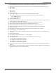
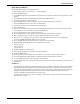
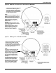
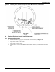
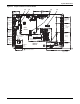
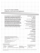
Figure 33 Jumper locations on Control Board
301471
Pg. 2, Rev. 3
1
1
1
1
1
1
1
1
1
1
1
1
1
1
1
1
1
1
1
1
1
1
1
Spare Digital
Outputs (Not
Used)
Call for
Cooling
Remote
Shutdown
Fan
Contactor
Output
Mother
Board
24VAC
Earth
Ground
Fan 4
Fan 3
Fan 2
Fan 1
CPU
Board
RS485
Communication
to Fans
Spare Analog
Outputs (Not Used)
Communication
from
indoor unit
Communication
from
indoor unit
CANbus
Service
Pressure
Inputs
Circuit 1
Circuit 2
Circuit 1
Circuit 2
Ambient
Temperature
Inputs
Alarm & Shutdown
Circuits
Ethernet and CANbus addressing
and signal indication
Indicator Lights: ON - Signal Present
Indicator Lights:
ON - Signal
Present
Control Fuses
RS485 Service
Terminal
BAR CODE
24VAC
CAUTION
For Continued Protection Against Risk of Fire,
Replace Only With Same Type and Rating of Fuse
ACM01M1
VER:A02
2010.08.10
BAR CODE
Human
Machine
Interface
(HMI)
Circuit 1
Circuit 2
F3 T3.15A, 250VAC
F2 T3.15A, 250VAC
ACM01U1 VER:A03 2010.08.10
1
1
Fuses are rated to 3A/250V
#1
#3
#2
J5
J2
J5J6J4