
Unit installation
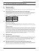

Microprocessor Control
37
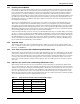
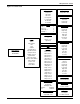
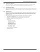
Figure 18 Control board—inside evaporator
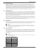
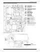
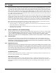
Figure 19 Wall box board
TB2-4 — Hot Gas Bypass
TB2-3 — High Head Alarm Connection
TB2-2 — Heat Rejection
TB2-1 — Heat Rejection
TB1-9 — Condensate Pump Aux Alarm
TB1-8 — Condensate Pump Aux Alarm
TB1-7 — Common Alarm
Connection
TB1-6 — Common Alarm
Connection
TB1-5 — Remote Shutdown
TB1-4 — Remote Shutdown
TB1-3 — Customer Alarm
Connection #2
TB1-2 — Customer Alarm
Connection #1
TB1-1 — Customer Alarm
Connection (common)
TB3-4 Connection to TB3 Pin 4 of
Wallbox
TB3-3 Connection to TB3 Pin 3 of
Wallbox
TB3-2 Connection to TB3 Pin 2 of
Wallbox
TB3-1 Connection to TB3 Pin 1 of
Wallbox
TB4-2 Site Monitoring Connnection (-)
TB4-1 Site Monitoring Connection (+)
P16 Remote Sensor Connection
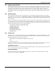
TB3 — 1
TB3 — 2
TB3 — 3
TB3 — 4
Wallbox
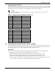
DIP Switches (1-8)