Precision Cooling For Business-Critical Continuity™ Liebert® XDP™ User Manual–50-60 Hz; 160kW Nominal Capacity
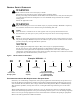
GENERAL SAFETY GUIDELINES ! WARNING Risk of electric shock. Can cause injury or death. Disconnect local and remote power supplies before working within. Before proceeding with installation of the XDP, read all instructions, verify that all the parts are included and check the nameplate to be sure the XDP voltage matches the available utility power. Follow all applicable codes. ! WARNING Risk of unit falling over. Can cause death, injury or property damage. The XDP is top-heavy.
TABLE OF CONTENTS GENERAL SAFETY GUIDELINES . . . . . . . . . . . . . . . . . . . . . . . . . . . . . . . . . . . INSIDE FRONT COVER 1.0 PRODUCT DESCRIPTION . . . . . . . . . . . . . . . . . . . . . . . . . . . . . . . . . . . . . . . . . . . . . . . . . . .1 1.1 General Product Information. . . . . . . . . . . . . . . . . . . . . . . . . . . . . . . . . . . . . . . . . . . . . . . . . . . 1 1.1.1 Product/System Description. . . . . . . . . . . . . . . . . . . . . . . . . . . . . . . . . . . . . . . . .
.3 Main Menu . . . . . . . . . . . . . . . . . . . . . . . . . . . . . . . . . . . . . . . . . . . . . . . . . . . . . . . . . . . . . . . . 21 4.3.1 4.3.2 4.3.3 4.3.4 4.3.5 4.3.6 4.3.7 4.3.8 4.3.9 4.3.10 4.3.11 4.3.12 4.3.13 4.3.14 4.3.15 4.3.16 Viewing or Changing Settings . . . . . . . . . . . . . . . . . . . . . . . . . . . . . . . . . . . . . . . . . . . . . . . . . . SETPOINTS . . . . . . . . . . . . . . . . . . . . . . . . . . . . . . . . . . . . . . . . . . . . . . . . . . . . . . . . . . . . . .
FIGURES Figure i Figure 1 Figure 2 Figure 3 Figure 4 Figure 5 Figure 6 Figure 7 Figure 8 Figure 9 Figure 10 Figure 11 Figure 12 Figure 13 Figure 14 Figure 15 Figure 16 Figure 17 Figure 18 Figure 19 Figure 20 Figure 21 Figure 22 Model number nomenclature . . . . . . . . . . . . . . . . . . . . . . . . . . . . . . . . . . . . . . . . . Inside Front Cover Liebert XDP components . . . . . . . . . . . . . . . . . . . . . . . . . . . . . . . . . . . . . . . . . . . . . . . . . . . . . . . . . .
iv
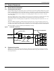
Product Description 1.0 PRODUCT DESCRIPTION 1.1 General Product Information 1.1.1 Product/System Description Liebert’s XDP refrigerant distribution unit is an interface between the building chilled water system and the cooling modules in the Liebert XD system. It is designed to circulate and control refrigerant to the cooling modules that are in the room with heat-producing equipment.
Product Description 1.3 Equipment Handling ! WARNING Risk of unit falling over. Can cause injury or death. The Liebert XDP is top-heavy. Use extreme caution and care when moving and installing this unit. NOTE Personnel should be properly trained and certified to move and rig equipment. 1.3.1 Handling With Skid • Always keep the unit upright, indoors and protected from damage. • If possible, transport the unit using a forklift truck. Otherwise use a crane with belts or cables.
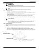
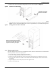
Product Description 4. Remove the two (2) end deck boards from one end of the pallet and the attached, notched section of the center runners (refer to Figure 3). Figure 3 Removing pallet boards for piano jack insertion Remove two deck boards ... ... and center runner sections from one end of pallet. 5. Place a piano jack with its forks snugly against the bottom of the unit and strap the Liebert XDP securely to the jack (refer to Figure 4).
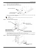
Product Description 8. Remove the runner from which all lag bolts have been removed (refer to Figure 6). Figure 6 Remove runner from pallet Slide this runner away from the Liebert XDP 9. Using the pallet jacks, raise the secured unit to the highest point that the piano jacks will allow. Once the unit has been raised, slide the remainder of the pallet from under the Liebert XDP (see Figure 7). Lower the Liebert XDP so that its base is approximately 1" (25.4mm) off the ground.
Product Description 1.4 Mechanical Considerations 1.4.1 Positioning the Liebert XDP Install the Liebert XDP according to the site specific documentation and secure the unit to the floor. The Liebert XDP can be installed near a wall or another Liebert XDP. However, there must be at least 3 feet (92cm) clearance in front of the Liebert XDP as service access for components in the unit.
Product Description Figure 9 Piping access points To first cooling module or bypass flow controller ** Install replaceable filter dryer assembly in liquid supply line B. * Orientation determined by installer. A - Return From Cooling Modules B - Supply to Cooling Modules 17-1/4" (438mm) 16-1/8" (410mm) 10" (254mm) 19" (483mm) Dimensions are approximate and subject to change without notice.
Product Description 1.5 Electrical Information 1.6 High Voltage Connections Make sure the actual supply voltage and frequency correspond to the voltage and frequency indicated on the Liebert XDP’s rating plate. The unit must be installed in accordance with national wiring regulations. Connect cables for high voltage supply to the electrical box in the Liebert XDP according to Figure 12 and make sure that the phases are correctly connected. ! WARNING Risk of electric shock. Can cause injury or death.
Product Description 2. Determine which knockouts in the electrical enclosure will be used and remove them (see Figure 11). Figure 11 Electrical enclosure knockout locations for field wiring User Interface (Wall Box) Wiring Liebert XD Module Condensate Connections (optional; depends on features supplied with Liebert XD Module) Temperature/Humidity Sensor Wiring Alternate Knockout for Temperature/Humidity Sensor Wiring Enclosure Cover Not Shown for Clarity 3.
Product Description Figure 13 High voltage connections—50Hz Customer Power Connection Ground Lug Disconnect Switch Transformer 2 Pump Circuit Breakers Busbar Power Block Fuse Blocks Transformer 1 Pump Contactors 1.7 Extra Low Voltage (ELV) Connections Extra Low Voltage power output is 30V and 100VA or less. 1. Turn off all unit power before connecting cables or wires. Failure to do so may damage this equipment (refer to Figure 14). 2.
Product Description Field Connections—All Units • Connect the control display panel cable to terminal block TB3 terminals 1 through 4 on the Liebert XDP control board as shown (refer to Figure 15). The display panel may be mounted on the Liebert XDP’s front right door if the Liebert XDP is located in the area that it conditions. The display panel must always be installed in the conditioned space.
Piping 2.0 PIPING 2.1 European Union Fluorinated Greenhouse Gas Requirements Stationary air conditioning, refrigeration, heat pump equipments and stationary fire protection systems in the European Community market and operating with fluorinated greenhouse gases (f-gas), such as R407C, R134a, R410A, must comply with the F-Gas Regulation: (EC) No. 842/2006 (F-gas). The regulation prohibits, among other actions, venting fluorinated greenhouse gases to the atmosphere.
Piping 2.3 Liebert XDP Interconnection with Liebert XD Cooling Modules All piping must be ASTM (American Society for Testing and Materials) Type L copper pipe. The Liebert XDP may be connected to Liebert XD cooling modules with either Liebert’s XD prefabricated piping assembly or with rigid, off-the-shelf piping. In either setup, piping for the Liebert XD system is arranged in a manner similar to piping for a chilled water system.
Piping Figure 17 Bypass flow controller details, dimensions 4” (102mm) 7/8” (22mm) ID Figure 18 Bypass flow controller arrangement 7/8" Refrigerant Grade Full Port Ball Valve Field-Supplied and Field-Installed Flow Direction Bypass Flow Controller (Field-Installed) Supply Main Figure 19 Bypass flow controller piping Liebert XD Cooling Module #1 Bypass Flow Controllers Coolant Supply Coolant Return Filter Dryer Assembly Liebert XDP or Liebert XDC 13 Liebert XD Cooling Module #2 Return Main
Piping 2.5 Piping Details—Shut-Off/Isolation Valves To allow for maintenance of the Liebert XDP, isolation valves must be installed on the chilled water circuit (see Figure 20). Figure 20 General piping details Return Supply Return Supply Liebert XDP A Liebert XDP B Floor Isolation valves Isolation valves Building Chilled Water Supply Building Chilled Water Return 2.5.1 Piping Installation Method All piping should be installed with high temperature brazed joints.
Piping 2.6 Checklist for Proper Installation ___ 1. ___ 2. ___ 3. ___ 4. ___ 5. ___ 6. ___ 7. ___ 8. ___ 9. ___ 10. Unpack and check received material. Position the Liebert XDP and secure it to the floor. Wire high voltage connections. Wire low voltage connections. Connect the building chilled water piping to the Liebert XDP. Connect the Liebert XD cooling module piping to the Liebert XDP. Check the system for leaks. Hold a vacuum on the system. Charge the system with refrigerant.
Checklist for Liebert XDP Startup 3.0 CHECKLIST FOR LIEBERT XDP STARTUP ! CAUTION Risk of piping and component rupture. May cause injury or equipment damage. Closing service valves may isolate liquid refrigerant, causing high pressure and rupture of piping. Do not close valves without following recommended procedures for repair, maintenance and replacement of components. Install pressure relief valves in field piping that may become isolated by service valves.
Checklist for Liebert XDP Startup If there is no “Loss of Flow” alarm present—This suggests that there is flow. Test the pressure differential by closing the ball valve on either the suction line or discharge line to stop the flow. This should prompt an alarm for “loss of flow on P1.” This alarm confirms that the switch has opened on low pressure (below 6 psi; 41kPa; 0.41 bars). If there is a “Loss of Flow” alarm present—This suggests that there is no flow.
Checklist for Liebert XDP Startup Table 6 System R-134a charge for a Liebert XDP with any model Liebert XDH/Liebert XDO/Liebert XDV/Liebert XDCF Refrigerant Charge, lb (kg) Per Liebert XD Unit (Excludes Connector Lines to and from Liebert XD Cooling Module) 157 lb. (65.7kg) Liebert XDP 3.55 lb. (0.66kg) Liebert XDO 2.32 lb. (1.05kg) Liebert XDV 5.32 lb. (2.41kg) Liebert XDH 1.41 lb. (0.
Checklist for Liebert XDP Startup 3.1.1 Calculating Refrigerant Charge—Example Using Tables 6, 7, 8 and 9, calculate the refrigerant charge of the individual sections of your Liebert XD system. Add the calculated charge amounts to determine the amount of R-134a refrigerant required for one system combining a Liebert XDP with Liebert XD cooling modules (Liebert XDCF, Liebert XDH, Liebert XDO and Liebert XDV). The example below combines one Liebert XDP with 20 Liebert XDV8 cooling modules.
Microprocessor Control 4.0 MICROPROCESSOR CONTROL 4.1 Feature Overview The microprocessor control for the Liebert XDP features an easy-to-use menu-driven LCD. The menus, control features and circuit board details are described in this section. Figure 22 User interface Up Arrow Key Status Display Down Arrow Key On/Off Key Alarm Silence Key Active alarms are displayed on the LCD screen and sound an audible beep. To silence an alarm, press the Alarm Silence/Help key as prompted on the display.
Microprocessor Control 4.2 Controls The Microprocessor Control for the Liebert XDP features an easy-to-use, menu-driven liquid crystal display. The menus, control features and circuit board details are described in this section. 4.2.1 Feature Overview The Liebert XDP maintains the refrigerant being pumped to Liebert XD cooling modules at a temperature above the room dew point, preventing condensation. 4.3 Main Menu Press the MENU key to display the Main Menu.
Microprocessor Control 4.3.
Microprocessor Control 4.3.6 TIME To change the time, press ENTER to select the function, then use the Up or Down arrow key to change the first character, press ENTER to store, then press the Up or Down arrow key to change the second character, press ENTER to store, etc. NOTE The clock uses the 24-hour system (for example, 17:00 would be 5:00 PM). The date and time are kept current even when the control board is not powered. 4.3.
Microprocessor Control PUMP WAIT TD The user may set the pump wait time delay to prevent the pump from continuing to run when refrigerant is not flowing. When the control detects a loss of refrigerant flow, the pump continues operating for the period specified in the PUMPWAIT TD. If refrigerant flow resumes during the specified interval, the pump will continue operating.
Microprocessor Control VALVE TIME This value is the number of seconds it takes the control valve to travel from fully closed to fully open. If the control loses the analog feedback position from the control valve, the control will close the valve, then calculate how long to open the valve for the current call for cooling. For example, if VALVE TIME is set to 60 seconds and there is a 50% call for cooling, the valve will open for 30 seconds, leaving the valve halfway open.
Microprocessor Control Change Password—SERVICE PASSWORD The factory default SERVICE PASSWORD is “123”—this password protects setup operations and more-critical alarm settings. To change the SERVICE PASSWORD: 1. 2. 3. 4. 5. 6. 7. 8. Press the MENU key to display the Main Menu. Use the Up or Down arrow key to scroll to the SERVICE PASSWORD function. Press ENTER to access the SERVICE PASSWORD function. The LCD will display three zeros (000). Enter the present, three-digit password. a.
Microprocessor Control 4.3.14 CUSTOM ALARMS This is the menu where the user selects the alarm message that will be displayed when there is an input to the customer alarm input on the control board. This menu has four choices: one user-defined custom message (see CUSTOM TEXT below for details) and three preprogrammed messages: • SMOKE DETECTED • CUSTOM 1 (default custom message. If the user enters a custom text message, that custom text will replace “CUSTOM 1.”) • WATER FLOW LOSS • STANDBY UNIT ON 1.
Alarm Descriptions and Solutions 5.0 ALARM DESCRIPTIONS AND SOLUTIONS 5.1 Alarm Descriptions NOTE Alarms must be acknowledged before they can be reset. To acknowledge or silence an alarm, press the ALARM SILENCE / ? key. • LOSS OF FLOW P1—Activated when Pump 1 is commanded to run and the differential pressure switch does not sense differential pressure (set at 6 psi; 41kPa; 0.41 bars).
Alarm Descriptions and Solutions • REFRIG SENS FAIL—Activated when the control stops receiving a signal from the refrigerant temperature sensor. If this alarm becomes active, the control will close the control valve over a 9-minute period. This alarm will shut down the Liebert XDP. Main power must be (disconnect switch) must be turned Off, then back On to clear this alarm. • LOSS OF POWER—Activated when the unit is On and operational and 24VAC power to the control is lost.
Alarm Descriptions and Solutions 5.3.2 Increase or Decrease Alarm Time Delays An alarm time delay is the time that the a condition must exist before the control activates an alarm for that condition. This can be used as a filter to prevent nuisance alarms from transient events.
Troubleshooting 6.0 TROUBLESHOOTING Table 16 Troubleshooting the XDP Symptom Possible Cause Check or Remedy No main power Check L1, L2 and L3 for rated voltage. Loose electrical connections Tighten connections. Overloads tripped Allow pump to cool. Check amp draw. Tripped circuit breaker Check circuit breaker to pump(s). Incorrect phase wiring See Table 5. No chilled water Check and verify that there is supply chilled water to the Liebert XDP.
Maintenance 7.0 MAINTENANCE The Liebert XD system components require little maintenance when proper fluid levels are maintained and proper startup and operation procedures are followed. The following tasks should be performed at the intervals stated: 1. Clean or replace chilled water strainer annually. Adjust accordingly based on purity of chilled water. 2. Check sight glass level of receiver every 4-6 weeks. During normal operation, the level should be at or above the second sight glass. 3.
Specifications 8.0 SPECIFICATIONS Table 17 Liebert XDP160 specifications Models XDP160RC--1 XDP160RA--1 160kW / 46 Tons, 60Hz XDP160RM--1 140kW / 40 Tons, 50Hz Each capacity is based on 45ºF (7ºC) entering water temperature and 140gpm (530lpm) water flow rate. Capacity is reduced when glycol mixtures are used in place of 100% water. Cooling Capacity, Nominal The Liebert XDP’s minimum recommended operating load is 20% of system nominal capacity.
Ensuring The High Availability 0f Mission-Critical Data And Applications. Emerson Network Power, the global leader in enabling business-critical continuity, ensures network resiliency and adaptability through a family of technologies—including Liebert power and cooling technologies—that protect and support business-critical systems. Liebert solutions employ an adaptive architecture that responds to changes in criticality, density and capacity.