Precision Cooling For Business-Critical Continuity™ Liebert® XDP™ with Liebert® iCOM® Control User Manual–50-60 Hz; 160kW Nominal Capacity
GENERAL SAFETY GUIDELINES ! WARNING Risk of electric shock. Can cause injury or death. Disconnect local and remote power supplies before working within. Before proceeding with installation of the XDP, read all instructions, verify that all the parts are included and check the nameplate to be sure the XDP voltage matches the available utility power. Follow all applicable codes. ! WARNING Risk of unit falling over. Can cause death, injury or property damage. The XDP is top-heavy.
TABLE OF CONTENTS GENERAL SAFETY GUIDELINES . . . . . . . . . . . . . . . . . . . . . . . . . . . . . . . . . . . INSIDE FRONT COVER 1.0 PRODUCT DESCRIPTION . . . . . . . . . . . . . . . . . . . . . . . . . . . . . . . . . . . . . . . . . . . . . . . . . . .1 1.1 General Product Information. . . . . . . . . . . . . . . . . . . . . . . . . . . . . . . . . . . . . . . . . . . . . . . . . . . 1 1.1.1 Product/System Description. . . . . . . . . . . . . . . . . . . . . . . . . . . . . . . . . . . . . . . . .
.5 Graphical Data Record. . . . . . . . . . . . . . . . . . . . . . . . . . . . . . . . . . . . . . . . . . . . . . . . . . . . . . . 26 4.6 Liebert iCOM Service Menu Icons and Legend . . . . . . . . . . . . . . . . . . . . . . . . . . . . . . . . . . . 27 5.0 START THE LIEBERT XDP WITH ICOM . . . . . . . . . . . . . . . . . . . . . . . . . . . . . . . . . . . . . . . 28 5.1 Checklist for Liebert XDP Startup . . . . . . . . . . . . . . . . . . . . . . . . . . . . . . . . . . . . . . . . . . . . .
FIGURES Figure i Figure 1 Figure 2 Figure 3 Figure 4 Figure 5 Figure 6 Figure 7 Figure 8 Figure 9 Figure 10 Figure 11 Figure 12 Figure 13 Figure 14 Figure 15 Figure 16 Figure 17 Figure 18 Figure 19 Figure 20 Figure 21 Figure 22 Figure 23 Figure 24 Figure 25 Figure 26 Figure 27 Figure 28 Figure 29 Figure 30 Figure 31 Figure 32 Model number nomenclature . . . . . . . . . . . . . . . . . . . . . . . . . . . . . . . . . . . . . . . . . Inside Front Cover Liebert XDP components . . . . . . . . . . . . . . . . .
TABLES Table 1 Table 2 Table 3 Table 4 Table 5 Table 6 Table 7 Table 8 Table 9 Table 10 Table 11 Table 12 Table 13 Table 14 Liebert XDP dimensions . . . . . . . . . . . . . . . . . . . . . . . . . . . . . . . . . . . . . . . . . . . . . . . . . . . . . . . . . . . 5 Unit piping outlet connection sizes, inches, OD Cu . . . . . . . . . . . . . . . . . . . . . . . . . . . . . . . . . . . . . 6 Supply, return pipe sizes for refrigerant loop . . . . . . . . . . . . . . . . . . . . . . . . . . . . . . . . . . .
Product Description 1.0 PRODUCT DESCRIPTION 1.1 General Product Information 1.1.1 Product/System Description Liebert’s XDP refrigerant distribution unit is an interface between the building chilled water system and the cooling modules in the Liebert XD system. It is designed to circulate and control refrigerant to the cooling modules that are in the room with heat-producing equipment.
Product Description 1.3 Equipment Handling ! WARNING Risk of unit falling over. Can cause injury or death. The Liebert XDP is top-heavy. Use extreme caution and care when moving and installing this unit. NOTE Personnel should be properly trained and certified to move and rig equipment. 1.3.1 Handling With Skid • Always keep the unit upright, indoors and protected from damage. • If possible, transport the unit using a forklift truck. Otherwise use a crane with belts or cables.
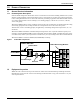
Product Description 4. Remove the two (2) end deck boards from one end of the pallet and the attached, notched section of the center runners (refer to Figure 3). Figure 3 Removing pallet boards for piano jack insertion Remove two deck boards ... ... and center runner sections from one end of pallet. 5. Place a piano jack with its forks snugly against the bottom of the unit and strap the Liebert XDP securely to the jack (refer to Figure 4).
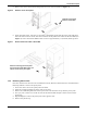
Product Description 8. Remove the runner from which all lag bolts have been removed (refer to Figure 6). Figure 6 Remove runner from pallet Slide this runner away from the Liebert XDP 9. Using the pallet jacks, raise the secured unit to the highest point that the piano jacks will allow. Once the unit has been raised, slide the remainder of the pallet from under the Liebert XDP (see Figure 7). Lower the Liebert XDP so that its base is approximately 1" (25.4mm) off the ground.
Installation 2.0 INSTALLATION 2.1 Mechanical Considerations 2.1.1 Positioning the Liebert XDP Install the Liebert XDP according to the site specific documentation and secure the unit to the floor. The Liebert XDP can be installed near a wall or another Liebert XDP. However, there must be at least 3 feet (92cm) clearance in front of the Liebert XDP as service access for components in the unit.
Installation Figure 9 Piping access points To first cooling module or bypass flow controller ** Install replaceable filter dryer assembly in liquid supply line B. Close this valve during normal operation Orientation defined by installer. * A - Return from cooling modules B - Supply to cooling modules 17-1/4" (438mm) Liebert recommends field-installation of shutoff valves at these points to permit isolating the Liebert XDP for maintenance. 16-1/8" (409.
Installation 2.2 Electrical Considerations Make sure the actual supply voltage and frequency correspond to the voltage and frequency indicated on the Liebert XDP’s rating plate. The unit must be installed in accordance with national wiring regulations. Connect cables for high voltage supply to the electrical box in the Liebert XDP according to Figure 12 and make sure that the phases are correctly connected. ! WARNING Risk of electric shock. Can cause injury or death.
Installation 2. Determine which knockouts in the electrical enclosure will be used and remove them (see Figure 11). Figure 11 Electrical enclosure knockout location for hazardous voltage wiring XDP Input Power Knockout Enclosure cover not shown for clarity 3. Route the input hazardous voltage electrical power wiring through the top left knockout (see Figure 11) to the disconnect switch L1, L2 and L3 (see Figures 12 and 13). Observe proper phasing. 4.
Installation Figure 13 High voltage connections—50Hz Customer Power Connection Ground Lug Transformer 2 Disconnect Switch Power Block Pump Circuit Breakers Transformer 6 Busbar Fuse Blocks Transformer 1 Pump Contactors 2.2.2 Extra Low Voltage (ELV) Connections Extra Low Voltage power output is 30V and 100VA or less. 1. Turn off all unit power before connecting cables or wires. Failure to do so may damage this equipment (refer to Figure 14). 2.
Installation 2.3 Remote Sensor Installation—Proper Placement Placement of the two remote temperature/humidity sensors is critical to effective cooling of the conditioned space. The remote sensors must be installed in areas where conditions are representative of the space conditioned by the Liebert XDP. Emerson recommends installing the sensors in different areas near the cooling modules served by the Liebert XDP.
Installation Figure 16 Connecting the remote temperature/humidity sensors Ribbon Cables Liebert IntelliSlot Power Supply P2 Liebert IntelliSlot 1 P1 Two Liebert IntelliSlots for optional OCWEB-LBDS Card or OC485-LBDS Card Liebert IntelliSlot 2 P65 Red Crossover Ethernet Cable Cable A 77 78 Cable B Not Used See Note 1 P61 P18 CAN Cable P63 E5 P64 P65 P32 P40 P66 P67 P3 P12 P11 P8 P7 P13 P33 P34 Liebert iCOM Microprocessor and I/O Board Crossover Coupler SW2 P39 P53 P52 P51 E1
Installation 2.3.1 DIP Switch and Jumper Settings for Remote Sensors The Liebert XDP is shipped with jumpers and DIP switch settings for normal operation. See Figure 17.
Installation 2.4 Field Connections—Optional for All Units • Connect field wiring from the optional Liebert XD cooling module condensation detection circuit to terminal strip locations COMM. (24) and H2O (51). • Connect optional field wiring from remote devices to remote alarm device, common alarm outputs, site monitor and remote shutdown, if applicable. See terminal strip descriptions in Figure 18.
Piping 3.0 PIPING 3.1 European Union Fluorinated Greenhouse Gas Requirements Stationary air conditioning, refrigeration, heat pump equipment and stationary fire protection systems in the European Community market and operating with fluorinated greenhouse gases (f-gas), such as R407C, R134a, R410A, must comply with the F-Gas Regulation: (EC) No. 842/2006 (F-gas). The regulation prohibits, among other actions, venting fluorinated greenhouse gases to the atmosphere.
Piping 3.3 Liebert XDP Interconnection with Liebert XD Cooling Modules All piping must be ASTM (American Society for Testing and Materials) Type L copper pipe. The Liebert XDP may be connected to Liebert XD cooling modules with either Liebert’s XD prefabricated piping assembly or with rigid, off-the-shelf piping. In either setup, piping for the Liebert XD system is arranged in a manner similar to piping for a chilled water system.
Piping Figure 20 Bypass flow controller details, dimensions 4” (102mm) 7/8” (22mm) ID Figure 21 Bypass flow controller arrangement 7/8" Refrigerant Grade Full Port Ball Valve Field-Supplied and Field-Installed Flow Direction Bypass Flow Controller (Field-Installed) Supply Main Figure 22 Bypass flow controller piping Liebert XD Cooling Module #1 Bypass Flow Controllers Coolant Supply Coolant Return Filter Dryer Assembly Liebert XDP or Liebert XDC 16 Liebert XD Cooling Module #2 Return Main
Piping 3.5 Piping Details—Shutoff/Isolation Valves To allow for maintenance of the Liebert XDP, isolation valves must be installed on the chilled water circuit (see Figure 23). Figure 23 General piping details Return Supply Return Liebert recommends field-installation of shutoff valves at these points to permit isolating the Liebert XDP for maintenance. Supply Liebert XDP A Liebert XDP B Floor Isolation valves Isolation valves Building Chilled Water Supply Building Chilled Water Return 3.5.
Piping 3.6 Filling the Pumped Circuit—R-134a Using a refrigerant pump or cylinder heater pads will speed the charging process. 1. Connect a charging manifold to the service port of the receiver outlet valve or to the suction and discharge side of the pump. 2. Purge the hoses. 3. Calculate the amount of R-134a refrigerant needed to charge the system, using the values in Tables 5, 6, 7 and 8; for assistance, refer to 3.6.1 - Calculating Refrigerant Charge— Example.
Piping Before beginning, verify that the system is not equipped with pre-charged flex pipe. Table 7 R-134a refrigerant charge for hard-piped connector lines to and from any model Liebert XDH/Liebert XDO/Liebert XDV/Liebert XDCF Refrigerant Charge, lb/foot (kg/m) Hard-Piped Connector Length and Diameter 0.08 (0.12) 1/2" OD Liebert XDO/Liebert XDH/Liebert XDV/Liebert XDCF supply connector actual length 0.13 (0.19) 5/8" OD copper tubing Liebert XDV/Liebert XDCF supply connector actual length 0.26 (0.
Piping 3.6.1 Calculating Refrigerant Charge—Example Using Tables 5, 6, 7 and 8, calculate the refrigerant charge of the individual sections of your Liebert XD system. Add the calculated charge amounts to determine the amount of R-134a refrigerant required for one system combining a Liebert XDP with Liebert XD cooling modules (Liebert XDCF, Liebert XDH, Liebert XDO and Liebert XDV). The example below combines one Liebert XDP with 20 Liebert XDV8 cooling modules.
Liebert iCOM Control 4.0 LIEBERT ICOM CONTROL 4.1 Liebert iCOM Components and Functions The Liebert iCOM controller layout is shown in Figure 24; the keyboard functions are defined in Table 11.
Liebert iCOM Control Table 11 Icon ? ESC Keyboard icons and functions Key Name Function On/Off Key Controls the operational state of the cooling unit. Alarm Key Silences an alarm. Help Key Accesses integrated Help menus. ESCape Key Returns to the previous display view. Enter Key Confirms all selections and selects icons or text. Increase Key (Up Arrow) Moves upward in a menu or increases the value of a selected parameter.
Liebert iCOM Control 4.2 Navigating Through the Liebert iCOM Display Liebert iCOM displays icons and text for monitoring and controlling your Liebert cooling unit. The Liebert iCOM’s home screen may be either simple, graphical (with bar graphs), simple comma (with decimal) or graphical comma (as in Figure 32). The default for the Liebert XDP is simple display (see Figure 25).
Liebert iCOM Control 4.2.2 Entering the Password Most settings in the Liebert iCOM are protected by a factory-set password, 1490. To enter the password: 1. 2. 3. 4. 5. 6. 7. From the home screen, press the Enter key to view the User Menu (see Figure 27). Press Enter again to highlight the first icon. Use the keyboard’s arrow keys to move to the icon for the data you wish to change. Once that icon is highlighted, press Enter again to open that menu. Press Enter to highlight the Password line.
Liebert iCOM Control 4.3 Changing Operational Settings Changes to the Liebert XDP’s operation settings in the Set Alarms and Setpoints menus require a password. 1. 2. 3. 4. 5. 6. 7. 8. 9. 10. From the home screen, press the Enter key to view the User Menu (see Figure 27). Press Enter again to highlight the first icon. Use the keyboard’s arrow keys to move to the icon for the data you wish to change. Once that icon is highlighted, press Enter again to open that menu. • If a password is required, see 4.2.
Liebert iCOM Control 4.4 Changing Liebert iCOM’s Display Settings No password is required to change the way Liebert iCOM displays data. The Display Setup controls how the unit shows data, such as temperature, date and time. To change the display settings: 1. 2. 3. 4. 5. 6. 7. 8. 9. From the home screen, press the Enter key to view the User Menu (see Figure 27). Press Enter again to highlight the first icon. Use the keyboard’s arrow keys to move to the Display Setup icon.
Liebert iCOM Control 4.6 Liebert iCOM Service Menu Icons and Legend Figure 29 Liebert iCOM Service Menu icons °C / °F % RH SET SET ALARMS WELLNESS Setpoints View and change operational setpoints Unit Diary Shows all program changes and maintenance performed, Maintenance/ Wellness Settings Shows all maintenance records, calculates next maintenance date NETWORK Network Setup or alter network setting.
Start the Liebert XDP with iCOM 5.0 START THE LIEBERT XDP WITH ICOM 5.1 Checklist for Liebert XDP Startup NOTICE Risk of piping and component rupture. May cause injury or equipment damage. Closing service valves may isolate liquid refrigerant, causing high pressure and rupture of piping. Do not close valves without following recommended procedures for repair, maintenance and replacement of components. Install pressure relief valves in field piping that may become isolated by service valves.
Start the Liebert XDP with iCOM 5.2 Starting the Liebert XDP with iCOM Controller The Liebert XDP is started, stopped and controlled through the Liebert iCOM controller. Figure 24 shows the Liebert iCOM keypad. 1. Turn On the fans of all the connected Liebert XD cooling modules. 2. Switch on power to the Liebert XDP with the main disconnect switch on the upper left corner of the unit. 3. Turn the On Liebert iCOM controller by pressing it’s I/O switch (see (Figure 24).
Operational Settings 6.0 OPERATIONAL SETTINGS The Liebert XDP with Liebert iCOM controller is configured at the factory with default values for various settings. Some may be altered for specific sites. 6.1 Using Liebert iCOM User Menu Icons The User Menu includes the following submenus, some of which may only be viewed and some which have settings that may be changed (see Figure 27 to view the icons on the User Menu).
Operational Settings Figure 31 Set Alarms submenu SET ALARMS (page 1 of 1) U201 U202 U203 U204 U205 U206 U207 U208 U209 U210 U211 UNIT 01 PASSWORD (Actual Level 0) High Room Air Temperature Low Room Air Temperature High Room Dewpoint High Refrigerant Temperature ???? 80.0°F 55.0°F 65.0°F 80.0°F High Chilled Water Temperature 60.
Alarm Descriptions and Solutions 7.0 ALARM DESCRIPTIONS AND SOLUTIONS 7.1 Alarm Descriptions NOTE Alarms must be acknowledged before they can be reset. To acknowledge or silence an alarm, press the ALARM key one time. This will silence the alarm; the red LED will remain illuminated until the alarm is reset. • HIGH TEMP SENSOR A—Activated when the remote temperature/humidity sensor designated as Sensor A detects that the temperature exceeds the setpoint.
Alarm Descriptions and Solutions • CONTROL VALVE FAILURE—Activated when the chilled water control valve has been commanded by the control to open or close and no change is detected from the valve-position signal. The control will close the valve and then try to control the control valve based on its travel time. Main power (disconnect switch) must be turned Off, then back On to clear this alarm.
Troubleshooting 8.0 TROUBLESHOOTING Table 13 Troubleshooting the XDP Symptom Pump will not energize Pump will not start or run Pump will not start Pump noisy Liebert XDP (Pump) suddenly stops Clogged filter/dryer and/or impeller Pipe rattle Possible Cause Check or Remedy No main power Check L1, L2 and L3 for rated voltage. Loose electrical connections Tighten connections. Overloads tripped Tripped circuit breaker Allow pump to cool. Check amp draw. Check circuit breaker to pump(s).
Maintenance 9.0 MAINTENANCE The Liebert XD system components require little maintenance when proper fluid levels are maintained and proper startup and operation procedures are followed. The following tasks should be performed at the intervals stated: 1. Clean or replace chilled water strainer annually. Adjust accordingly based on purity of chilled water. 2. Check sight glass level of receiver every 4-6 weeks. During normal operation, the level should be at or above the second sight glass. 3.
Specifications 10.0 SPECIFICATIONS Table 14 Liebert XDP160 specifications Models XDP160RC--3 XDP160RA--3 160kW / 46 Tons, 60Hz XDP160RM--3 140kW / 40 Tons, 50Hz Each capacity is based on 45ºF (7ºC) entering water temperature and 140gpm (530lpm) water flow rate. Capacity is reduced when glycol mixtures are used in place of 100% water. Cooling Capacity, Nominal The Liebert XDP’s minimum recommended operating load is 20% of system nominal capacity.
Ensuring The High Availability Of Mission-Critical Data And Applications. Emerson Network Power, the global leader in enabling business-critical continuity, ensures network resiliency and adaptability through a family of technologies—including Liebert power and cooling technologies—that protect and support business-critical systems. Liebert solutions employ an adaptive architecture that responds to changes in criticality, density and capacity.