
Surge Protector User Manual

Operation
41
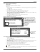
10.3 Navigating Through the iCOM Display
iCOM displays icons and text for monitoring and controlling your Liebert cooling unit. The iCOM’s
default screen may be either graphical or simple (no bar graphs).
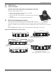
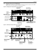
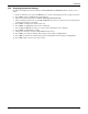
Figure 30 iCOM graphical display default screen components
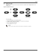
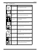
Figure 31 iCOM simple display default screen components
UNIT 1 UNIT ON
T
ACT
72°F
73°F
T
95°F 50%
%
VENT
kW 10
11/07
100%
30%
OK NO
Internal
Cabinet
Setpoint
Actual Ambient
Temperature
Actual Internal
Cabinet Temperature
Evaporator Fans
Actual Ambient
Relative Humidity
Percent Cooling
Next Scheduled
Maintenance
Open Door Operation
(only one icon
shows at a time)
Optional Load Monitor Readout
(amount of energy consumption
by internal equipment)
Backup
Ventilation
(shows only
when
operating)
UNIT ON
T
ACT
72°F
73°F
T
95°F 50%
%
VENT
100%
OK NO
kW
10
11/07130%
UNIT 1
Internal
Cabinet
Setpoint
Actual Ambient
Temperature
Actual Internal
Cabinet Temperature
Evaporator Fan
Operation
Actual Ambient
Relative Humidity
Percent
Cooling
Next Scheduled
Maintenance
Open Door Operation
(only one icon
shows at a time)
Optional Load Monitor
Readout (energy con-
sumption by internal
equipment)
Active Alarms
(not displayed
when there are no
active alarms)
Backup Ventilation
(shows only when
operating)