
User manual

Installation
12
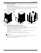
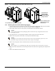
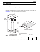
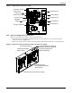
Figure 10 Electrical enclosure knockout location for hazardous voltage wiring
3. Route the input hazardous voltage electrical power wiring through the top left knockout (see
Figure 10) to the disconnect switch L1, L2 and L3 (see Figures 11 and 12). Observe proper
phasing.
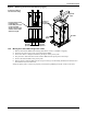
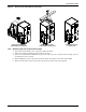
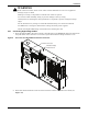
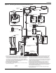
4. Connect the ground wire to the ground lug (see Figures 11 and 12), which is in the middle left of
the enclosure.
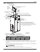
Figure 11 High voltage connections—60Hz
XDP Input Power
Knockout
Enclosure Cover
Not Shown for Clarity
Customer
Power
Connection
Ground
Lug
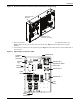
Fused
Disconnect
Fuse
Blocks
Fuse
Block
Power Block
Pump
Contactors
Transformer 2
(Supplied on 460V
Units Only)
Transformer 6
Transformer 1