MONITORING LIQUI-TECT MONITORING SYSTEM USER MANUAL
TABLE OF CONTENTS 1.0 INTRODUCTION 1.1 1.2 1.3 1.4 1.5 Equipment Inspection . . . . . . . . . . . . . . . . . . . . . . . . . . . . . . . . . . . . . . . . . . . . . . . . . . . . . . . . Outside Enclosure Overview . . . . . . . . . . . . . . . . . . . . . . . . . . . . . . . . . . . . . . . . . . . . . . . . . . . Typical Sequence . . . . . . . . . . . . . . . . . . . . . . . . . . . . . . . . . . . . . . . . . . . . . . . . . . . . . . . . . . . . Controller Board Overview . . . . . . . . . . . . . . .
6.4 6.5 Setup System - Setup ZN2 Zone 2 . . . . . . . . . . . . . . . . . . . . . . . . . . . . . . . . . . . . . . . . . . . . . . 29 Setup System - Setup Alarm Outputs . . . . . . . . . . . . . . . . . . . . . . . . . . . . . . . . . . . . . . . . . . . 30 6.5.1 6.5.2 6.5.3 Specify Longest Cable Length . . . . . . . . . . . . . . . . . . . . . . . . . . . . . . . . . . . . . . . . . . . . . . . . . . 31 Define Relays as Normally Open or Normally Closed . . . . . . . . . . . . . . . . . . . . . . . . . .
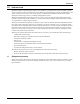
Introduction 1.0 INTRODUCTION The Liebert Liqui-tect Monitoring System is the ultimate in leak detection and retrofitting capabilities for computer rooms and other large areas. The Liqui-tect Monitoring System provides direct-read at the control unit location, as well as the ability to communicate with the Liebert SiteScan Web enterprise monitoring system or a building management system.
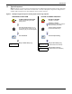
Introduction 1.2 Outside Enclosure Overview The enclosure for the Liqui-tect panel’s controller board comes in two sizes: • The large enclosure is designed to accommodate the Transformer Module and future components, in addition to the controller board. • The small enclosure is built to hold the controller board only. Both enclosures are 2-3/4" deep. Both enclosures have a built-in liquid crystal display (LCD) and a key lock, as shown in the example below.
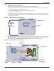
Introduction 1.3 Typical Sequence Figure 3 shows a typical sequence of how the Liqui-tect Monitoring System functions after detecting a leak, contamination or cable break in either Zone 1 or Zone 2. Responses depend on configuration settings. This example shows what happens when a leak is detected. Figure 3 Example of typical sequence: Analog input reaches high setpoint RESPONSES TO AN ALARM LIQUI-TECT PANEL 05-SEP-02 14:04:13 V5.100.
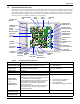
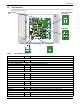
Introduction 1.4 Controller Board Overview The Liqui-tect panel’s controller board, as shown below, has connectors for two digital outputs for leak detection alarms, two digital outputs for cable break alarms, two inputs for leak detection cables and two analog outputs for connecting to a building management system. The board comes complete with light-emitting diodes (LEDs) to display the status of monitored zones, power connections and other features necessary to monitor and protect your operation.
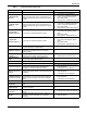
Introduction Table 1 Controller board components Item H-Status LEDs Description Indicates the operational status of the panel. I-4/20mA output (Zone 2) Provides the distance liquid is detected, normal status and cable fault. Used to provide status to a building management system or remote monitoring system. J-4/20mA output (Zone 1) Provides the distance liquid is detected, normal status and cable fault. Used to provide status to a building management system or remote monitoring system.
Introduction 1.5 LED Indicators The Liqui-tect panel’s controller board has LED indicators that show the status of inputs, outputs and other board components.
Installation 2.0 INSTALLATION 2.1 Installation Considerations The Liqui-tect panel must be installed indoors and may be mounted on the surface of a wall or flushmounted, depending on the user’s application and the type of wall the unit will be mounted on. The unit’s location must meet the following criteria: • The panel must be placed close enough to the areas to be monitored to permit proper connection of the leak detection cable.
Installation 2.2 Surface-Mounting the Liqui-tect Panel NOTE Removing the conduit knockouts before mounting the Liqui-tect panel on the wall will ease installation and prevent strain on the mounting hardware and wall. It is imperative to remove the knockouts if the unit is to be flush-mounted. After determining where to place the unit, check to ensure that you have all the hardware required to install the panel on the surface of a wall. Obtain the needed tools and material. Required tools • • • • 2.2.
Installation 2.3 Flush-Mounting the Liqui-tect Panel NOTE Removing the conduit knockouts before mounting the Liqui-tect panel on the wall will ease installation and prevent strain on the mounting hardware and wall. It is imperative to remove the knockouts if the unit is to be flush-mounted. The rectangular access doors on the top and bottom of the Liqui-tect panel must be removed from the outside of the panel and reinstalled on the inside of the panel.
Installation 2.4 Connect Power to the Liqui-tect Panel The Liqui-tect panel requires 24VAC for proper operation. Liebert recommends using the optional Transformer Module manufactured by Liebert or another UL-approved Class 2 power unit to obtain proper voltage. If the power unit is not a Class 2 circuit, it must be protected with an IEC 5 x 20mm time lag 2A fuse. For information, consult your local dealer, Liebert representative or the Liebert Worldwide Support Group.
Installation 2.4.2 Input and Output Power Connections - Large Enclosure ! CAUTION ! WARNING The 115VAC/230VAC Transformer Module must be connected to a branch circuit with 15A branch circuit protection. This equipment is intended to be installed by a qualified and certified electrician who must review and approve customer supplied wiring and circuit breakers, verify correct input and grounded connections to ensure compliance with the technical standards and national and local electrical codes.
Connections and Configuration 3.0 CONNECTIONS AND CONFIGURATION CAUTION ! Be sure that the power wiring is disconnected from the Liqui-tect panel before installing any wiring to this unit or changing input or output connections. Input and output connections to the Liqui-tect panel may be made in any order—it is not necessary, for example, to make all input connections before making any output connections. Use copper conductors only for all wiring.
Connections and Configuration 3.1 Connecting Leak Detection Cable Inputs The leak detection cable inputs are found on the lower right side of the Liqui-tect panel’s printed wiring assembly board. There are two terminal blocks for the inputs; the lower terminal block is for the Zone 1 cable and the terminal block above it is for a second leak detection cable, Zone 2. To determine the proper wire size, see Table 4 - Wiring specifications.
Connections and Configuration 3.1.2 Connecting Leak Detection Cable to the Connection Cable The connection cable has a black fitting on one end that will fasten securely to the fitting on one end of the leak detection cable—see Figure 8. Push these ends together, being careful to insert the protruding ends of the leak detection cable into the holes in the connection cable connector. Twist the connector ring to securely link the cables.
Connections and Configuration 3. Once the cable passes the test, lay it in the pattern desired. Pay special attention to the following cable placement precautions. DETECTION CABLE PLACEMENT PRECAUTIONS • Do not use detection cable that is damaged or dirty—for example, from plaster, spackle or debris. • Detection cable should not be dragged through contaminants (dirty or greasy areas).
Connections and Configuration 3.2 Connecting Alarm Outputs The Zone 1 and Zone 2 alarm outputs, found in the top right corner of the Liqui-tect panel, provide a contact output for a leak and a cable break for each zone. As an example, the outputs may provide alarms to an auxiliary alarm panel or building management system. To determine the proper wire size, see Table 4 - Wiring specifications.
Connections and Configuration 3.4 RS422 SiteScan Web Connector The Liqui-tect panel will interface with Liebert’s SiteScan Web enterprise monitoring system. SiteScan can be used to monitor the Liqui-tect panel from a host computer and silence the audible alarm. The terminal block connector, TB8, is on the bottom edge of the board, near the left corner. To connect the SiteScan Web to the Liqui-tect panel: 1. Disconnect electrical power to the Liqui-tect panel. 2.
Overview of Menus 4.0 OVERVIEW OF MENUS The Liqui-tect panel displays the Opening Screen at startup, as shown in Figure 14. If any alarms are active, the Current Alarm screen appears. (Pressing any key on the LCD keypad will silence the audible alarm.) If no alarms are present, the LCD screen will alternately display the Opening Screen and a screen showing NO ALARMS PRESENT.
View Status Options 5.0 VIEW STATUS OPTIONS The View Status menu allows any user to view the status of cables in both zones, an alarm history log and a trend log for both zones. The arrows ↑↓ are used to scroll through the menu. The Enter ↵ key is used to select the menu item. This section presents step-by-step instructions for each of the following options: • View Cable Status • View Alarm History • View Zone Trend Figure 15 shows the main options available from the View Status menu.
View Status Options 5.1 View Cable Status Main Menu The Cable Status screens display the overall status of the cable connected to each of the two zones monitored by the Liqui-tect panel, as well as the length of the cable being monitored and the amount of current present in each cable.
View Status Options 5.2 View Alarm History Main Menu The Alarm History Log contains up to 100 records of alarms that have occurred. Records are added to this log as alarms occur. > VIEW STATUS SYSTEM AND CONTROL To view the Alarm History Log: ↑↓=NEXT • From the Main Menu, use the arrows ↑↓ to choose View Status, then press Enter ↵. • From the View Status Menu, use the arrows ↑↓ to choose View Alarm History, then press Enter ↵. 5.2.
View Status Options 5.3 View Zone Trend Main Menu The Zone Trend Log contains up to 288 records that are recorded at regular intervals (every 24 hours) to assist users with verifying operational and troubleshooting problems. Records are added the beginning of the log as they occur. To view the Zone Trend Log: ↑↓=NEXT ↵=SELECT View Status Menu • From the Main Menu, use the arrows ↑↓ to choose View Status, then press Enter ↵.
System and Control Options 6.0 SYSTEM AND CONTROL OPTIONS The System and Control menu allows you to configure the Liqui-tect panel—setting up inputs and outputs and system features such as date and time. This menu also provides a vehicle for mapping points, clearing latched alarms and deleting records from the Liqui-tect panel’s alarm and trend logs. The arrows ↑↓ are used to scroll through the menu. The Enter ↵ key is used to select the menu item and enter new information.
System and Control Options Figure 16 shows the main options available from the System & Control menu. Figure 16 Menu overview - System and Control menu Opening Screen LIQUI-TECT PANEL DD-MON-YY HR:MM:SS VERSION X.X.
System and Control Options 6.2 Setup System - Overview The Setup System screen displays six options that allow you to configure zones with cable, alarm outputs, the re-alarm delay time, log points to create a map and system details, such as changing the login password or the system date and time: • • • • • • 6.
System and Control Options 6.3.1 Identify the Zone as Connected Setup Zone 1 Menu To make use of the zone ZN1, you must specify it as Connected (Y). By default, ZN1 is Not connected (N). See 3.1 - Connecting Leak Detection Cable Inputs for instructions on connecting the cable to this zone. • From the Setup Zone 1 Menu, choose Connected, as shown at right, and press Enter ↵. • To change this feature, use the arrows ↑↓ to choose Y (Yes - Connected) or N (No - Not connected), then press Enter ↵.
System and Control Options 6.3.4 Auto Calibration Setup Zone 1 Menu The auto calibration feature is designed to allow compensation for the resistance tolerances in the two legs of the sensing wires. As soon as cable is connected, the panel begins calculating the cable length. Initiating the auto calibration feature allows the user to modify the distance to account for any discrepancies.
System and Control Options 6.3.6 Set Up Sensitivity for Contamination Detection Each zone may be set up with a sensitivity level at which contamination on the cable is detected. Examples are construction debris and dust. • The most sensitive setting is 20 µA—light contamination will trigger an alarm. • The least sensitive setting is 300 µA. This setting requires heavy contamination to activate an alarm. Increase the setting if nuisance alarms occur.
System and Control Options 6.4 Setup System - Setup ZN2 Zone 2 Setup System Menu NOTE The setup options are identical for both zones, except the name of the zone differs. The Liqui-tect panel has two independent zones—ZN1 and ZN2—that may be configured individually. Each zone can monitor up to 5,000 ft. (1524m) of leak detection cable.
System and Control Options 6.
System and Control Options 6.5.1 Specify Longest Cable Length You may specify the length of the longest cable connected to either of the 4-20mA alarm outputs. The default value is 0-1000 ft. (0-304.8m). Valid entries range from 0-500 ft. (0-152.4m) to 0-5000 ft. (0-1524m), as shown in the Maximum Cable Length screen, below right. Select the longer cable length installed on either zone. For example, if Zone 1 has 2000 ft. (609.6m) of cable and Zone 2 has 3500 ft. (1066.8m), select 0-4000 ft. (0-1219.2m).
System and Control Options Following are some similarities and differences between Latched and Unlatched alarms. Liqui-tect System’s Response to Alarms - Both Latched and Unlatched When a leak or cable break is detected: • An alarm occurs, • A record is created in the Alarm History Log and • The leak-detected or cable-break alarm output contact changes state. Latched Alarms Only The user must reset latched alarms before another leak or cable break alarm can occur.
System and Control Options 6.7 Setup System - Setup Mapmode Mapping involves measuring the exact location of various points along the leak detection cable. This greatly simplifies the use of the Liqui-tect Monitoring System to quickly pinpoint the location of a leak. The Liqui-tect Monitoring System determines the location of a leak by computing its distance along the leak detection cable.
System and Control Options 6.7.1 View Last Map Setup System Menu The View Last Map option allows you to review the mapped points from the last mapping of a zone. This feature is the data logger for the mapmode process described in the previous section, 6.7 - Setup System - Setup Mapmode.
System and Control Options 6.
System and Control Options 6.8.2 Change Date & Time/Automatic Daylight Saving Time The Liqui-tect panel has a built-in, real-time clock that is backed up by an encapsulated lithium battery and set up to adjust automatically for daylight saving time twice a year. The Setup System Info menu allows you to change the date or time or automatic adjustment at any time.
System and Control Options 6.9 Reset Latched Alarms Main Menu The Reset Latched Alarms menu allows you to clear any leak or fault alarms that have been defined as latched. VIEW STATUS > SYSTEM AND CONTROL To clear latched alarms: ↵=SELECT ↑↓=NEXT Log In and Choose Reset Latched Alarm • From the Main Menu, use the arrows ↑↓ to choose System and Control, then press Enter ↵ (see 6.1 - Login for help). • Enter your password at the Login screen.
System and Control Options 6.10 Clear Alarm History Main Menu The Clear Alarm History menu allows you to delete all records from the Alarm History Log, which contains up to 100 records of alarms that have occurred. To delete all records from the Alarm History Log: VIEW STATUS > SYSTEM AND CONTROL ↵=SELECT ↑↓=NEXT Login Log In and Choose Clear Alarm History • From the Main Menu, use the arrows ↑↓ to choose System and Control, then press Enter ↵ (see 6.1 - Login for help).
System and Control Options 6.11 Clear Zone Trend Main Menu The Clear Zone Trend menu allows you to delete all records from the Zone Trend Log, which contains up to 288 records. These records are created every 24 hours to assist in troubleshooting. To delete all records from the Zone Trend Log: VIEW STATUS > SYSTEM AND CONTROL ↑↓=NEXT ↵=SELECT Login Log In and Choose Clear Zone Trend • From the Main Menu, use the arrows ↑↓ to choose System and Control, then press Enter ↵ (see 6.1 - Login for help).
Specifications 7.0 SPECIFICATIONS 7.1 Liqui-tect Panel Specifications Small Enclosure Power Requirements Large Enclosure LPS0240 115VAC LPL1150 230VAC LPL2300 24VAC ±10% of nominal; 50/60 Hz, 0.3A, 8VA 115VAC ±10% of nominal; 60 Hz, 4A, 460VA 230VAC ±10% of nominal; 50 Hz, 0.5A, 115VA Dimensions W x D x H, in. (mm) 14-1/4 x 2-3/4 x 12 (361.95 x 69.85 x 304.8) 18 x 2-3/4 x 18 (457.2 x 69.85 x 457.2) Weight (Assembled) 7.68 lb. (3.48 kg) 20.56 lb. (9.
Specifications NOTES 41
Specifications 42
MONITORING LIQUI-TECT MONITORING SYSTEM The Company Behind the Products With over a million installations around the globe, Liebert is the world leader in computer protection systems.