
Satellite Radio User Manual


Installation Manual 27
Wiring the Transmitter to the Sensor
Installing the Transmitter Output Wiring – AnalogSensor WiringBefore You Begin
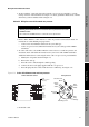
8. At the transmitter, connect the four wires from the core processor to terminals 1–4 on the
mating connector of the transmitter. See Figure 3-2. Never ground the shield, braid, or shield
drain wire(s) at the transmitter. Refer to Figure 2-4.
Subtask 2: Wiring the sensor to the remote core processor
1. Refer to Micro Motion’s 9-Wire Flowmeter Cable Preparation and Installation Guide for
instructions on cable shielding and preparation:
• At the sensor end, follow the instructions for your cable type.
• At the core processor end, follow the instructions for your cable type with an MVD
transmitter.
2. To connect the wires, refer to Micro Motion’s 9-Wire Flowmeter Cable Preparation and
Installation Guide and follow the instructions for your sensor with an MVD transmitter.
Additional information for connecting the wires at the core processor is provided below:
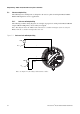
a. Identify the components shown in Figure 2-8.
b. Remove the end-cap.
c. Insert the 9-wire cable through the conduit opening.
d. Connect the wires to the plugs supplied with the core processor.
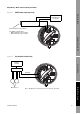
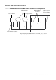
e. Insert the plugs into the sockets inside the lower conduit ring. See Figure 3-12.
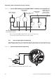
Figure 3-12 9-wire cable between sensor and core processor
3. Ground the cable.
CAUTION
Allowing the shield drain wires to contact the sensor junction box can cause
flowmeter errors.
Do not allow the shield drain wires to contact the sensor junction box.
Brown
Red
Green
White
Blue
Gray
Orange
Violet
Ye l l o w
Black
(Drains from all
wire sets)
Plug and
socket
Mounting screw
Blue
Gray
Orange
Red
Green
White
Brown
Violet
Yellow
Ground screw
Black
9-wire cable from sensor Core processor