MILLENNIUM II Multi-Channel Transmitter User Manual Single or Dual Channel PartNumber: Number:MAN-0076 MAN-0076 Rev 05 Part Rev Aprl December 07, 2012 2008
IMPORTANT INFORMATION This manual is for informational purposes only. Although every effort has been made to ensure the correctness of the information, technical inaccuracies may occur and periodic changes may be made without notice. Net Safety Monitoring Inc., assumes no responsibility for any errors contained within this manual.
TABLE OF CONTENTS IMPORTANT INFORMATION ...................................................................................................................................................... 2 WARRANTY...................................................................................................................................................................................... 2 CONTACT INFORMATION ..........................................................................................................
.2.8 Select Display Language ................................................................................................................................................. 30 4.2.9 MODBUS Setup ............................................................................................................................................................... 30 4.3.0 Setup Current Date ..............................................................................................................................
INTRODUCTION Building on the outstanding legacy of the Millennium Series, Net Safety’s latest innovation in this line of continuously evolving industrial transmitters and sensors, the Millennium II, pushes the boundaries of what you can expect from your detection system. Combined with state of the art “Smart” sensors, users will receive a detection system which is both versatile and reliable for fast, accurate and continuous monitoring of gases in extreme environments.
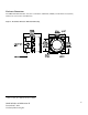
Enclosure Dimensions The Millennium II Transmitter enclosure is available in Aluminum (AL6061) and Stainless Steel (SS316). Dimensions are in inches and millimeters.
SECTION 1: Installation 1.1 Unpack Carefully remove all components from the packaging and check them against the enclosed packing list. Inspect all components for obvious damage such as broken or loose parts. If you find any components missing or damaged, notify the representative or Net Safety Monitoring, immediately. 1.2 Mounting Ensure transmitter and sensor are securely mounted, taking into consideration all requirements.
1.2.2 Transmitter electronics module and Relay options The transmitter electronics module may be equipped with 4 electromechanical relays or 4 solid-state relays which are mounted to the main terminal board via plastic standoffs. Relay boards are field replaceable by simply unlocking the plastic standoffs with a small flat head screw driver. Remove relay board after unlocking standoffs, insert the replacement relay board, and then lock the plastic standoff with the screw driver.
1.2.3 Rotating electronics module relative to enclosure and conduit entries The electronics module consists of the relay board and faceplate (Display/CPU assembly) with main terminal board. To rotate the electronics module, follow these instructions: 1. 2. 3. 4. 5. 6. 7. 8. 9. 10. 11. 12. 13. 14. Turn off power to transmitter and ensure area is de-classified. Remove the enclosure cover. Unscrew both the locking knobs and free from two metal standoffs. Lift transmitter faceplate from enclosure.
SECTION 2: Wiring and installation 2.1 Field Installation Warning Wiring codes and regulations may vary. ATEX requires that supply connection wiring must be rated at least 5°C above the maximum ambient temperature of 85°C. Wiring must comply with all applicable regulations relating to the installation of electrical equipment in a hazardous area and is the responsibility of the installer. If in doubt, consult qualified personnel before wiring the system.
It is the responsibility of the installer to install conduit seals where necessary, and to design conduit runs to ensure that condensation does not accumulate and collect inside the enclosure. 2.1.2 Cable choice and guidelines Radio Frequency Interference (RFI) can be caused by nearby electrical devices (transformers, high voltage equipment) as well as handheld communications devices/radios, which when activated, may impede the proper functioning of the transmitter and sensor.
Armored Cable preparation procedure: 1. Prepare the armored instrument cable as illustrated in Figure 5 and follow all assembly and/or preparation instructions provided by the cable and/or cable gland manufacturer. 2. Install cable gland and reducer onto the cable. 3. Ensure four (4) inches of wire length is available for connecting to terminals inside the junction box. 4. Use a small flat head screw driver when connecting wires to connector terminals. See Figure 6. 5.
Warning Before wiring, ensure that power to transmitter is switched off. When connecting cable wires, use a small screwdriver to gently press down and hold the spring connector open. Insert the appropriate wire into the open connector hole, releasing the screwdriver to secure the wire. See Figure 6. Figure 6: Connecting wires Warning Avoid touching electronic components, as they are susceptible to electrostatic discharge (ESD). Refer to Appendix A, “Electrostatic Sensitive Device (ESD)”. 2.1.
2.1.4 Remotely mounted sensors jumper configuration Sensor separation from the transmitter may extend up to 2000 feet in which case a junction box is required. When mounting sensor remotely (separating sensor from transmitter), Jumpers JP1 and JP2 should be installed over the pins. Jumpers and pins are located on the main terminal board near the sensor terminals. JP1 is for channel 1 and JP2 is for channel 2. Refer to Figure 8.
2.1.5 Sensor and Transmitter terminals Warning Before wiring, ensure power to the unit is switched off. Connect the sensor wires to the sensor terminals of the transmitter and connect the transmitter’s power and output terminals to the wiring leading to the Power source/panel. Refer to the configuration tables below for sensor as well as transmitter power and output terminal designations.
2.1.6 Remote Reset If the alarm relays are configured for latching operation it may be desirable to reset latched alarms from a remote location. In this case a normally open, momentary push-button switch may be connected across terminals RST and COM. Figure 10: Remote Reset wiring 2.1.
2.1.8 Wiring drawings Wiring drawings show general ways in wiring the system for analog signal output. Consult qualified personnel on specific wiring requirements.
Figure 13: Isolated terminal connection 18 MAN-0076 Rev 05 Millennium II December 07, 2012 Net Safety Monitoring Inc
2.1.9 Installation Checklist Prior to operation, it is important to do the following checks. Ensure transmitter and sensor are properly and firmly mounted. Ensure that the enclosure certified stopping plug is tightened to unused conduit entry/opening, to maintain ingress protection and flameproof type protection. Ensure transmitter and sensor are not being obstructed; transmitter and sensor are accessible and target gas is not inhibited from reaching sensor.
SECTION 3: Transmitter and faceplate description 3.1 Transmitter Power Up After power is applied to the transmitter, a warm-up routine will begin, the duration of which depends on the sensor type. The display will indicate the sensor warming up and the Status LED will flash Slow Red and current output will be 3.0mA. After the warm-up period, the transmitter will enter normal operation and the screen will display: “Channel 1 00 %LEL (or PPM), Channel 2 00 %LEL (or PPM).
3.3 Status LED The Status LED can be solid Red or Green, or flashing Red or Green to indicate various states of the transmitter and sensor. Refer to “Sensor Status Registers, Status LEDs, Current Loop, and Display Messages”. 3.4 Current loop measurement (Test jacks) For convenience, a pair of test jacks for each analog output is provided on the front face of the display module. Attach mA meter probes to these jacks to check loop current without opening the circuit to insert the meter.
SECTION 4: Operation 4.1 Menu options The main menu provides access to various functional settings/options, as seen in the Table 2 below. Each menu option has a submenu, whereby configuration is done. Table 2: Main menu options Calibrate Sensor Enable/Disable Channels Set Alarm Level Set Relay Option Relay Assignment Relay Alarm Mode setting Select Display Language Modbus Setup Setup Current Date Setup Current Time View Events Log Manual Reset Self-test Relay Sensor Upper Limit(Range) Select Gas Type Cal.
Sub menu Figure 17: Menu structure flow chart Activate any menu button then select ‘yes’ with menu button 1 to enter main menu Calibrate sensor? Activate menu button 3 to display sub menu) Sub menu Calibrate sensor 1 Calibrate sensor 2 Exit (Navigate with 1 & 2, select with button 3. See pages 24, 25 & 26). Hour, minutes (Navigate with 1& 2, select with button 3. See pages 31 &32).
4.2.1 Full calibration (Normal calibration) procedure Prior to attempting calibration read and understand the calibration procedure below. Also see Figure 18 for additional reference. The following calibration procedure should be followed to ensure an accurate correlation between the output signal and the gas concentration. For accurate performance, the Millennium II is calibrated using 50% span gas.
4.2.2 (Cont’d) Zero calibration option The “Zero” calibration option is selected if the sensor is only being zeroed (this not a complete calibration) It does not require the application of span gas, as only the sensor’s zero point is adjusted. Ensure that no contaminants are present, if the surrounding air is to be used for Zeroing. If Zero calibration is needed, at step 7 above, select ‘Zero’ using switch 3).
Figure 18: Calibration Flow chart Calibration Procedure Purge system with clean air from canister, then remove air canister Calibration complete Activate any menu button Span Failed. Perform manual reset. See page 32. Repeat calibration .proceure. Enter Main Menu rate Sensor? YES Remove Calibration Gas NO Activate menu button 1 to select yes YES NO Span successful? CH1: Spanning LEL / ppm reading Calibrate Sensor? Note: Some sensor types can be calibrated with 10% - 60% span calibration gas. Cal.
4.2.3 Enable / Disable channels This option allows the Millennium II Transmitter channels to be enabled or disabled. The default value is channel 1(CH1) enabled for single sensor models while channel 2(CH2) is permanently disabled. Both channels are enabled for two sensor models. 1. Enter the main menu by selecting/activating any key to get the “enter main menu” prompt, then activate switch 1 to select “yes”. 2. Select the down arrow key (switch 2) with the magnet, and scroll to “Enable/Disable Channel?” 3.
10. Apply test gas to confirm alarm level settings. Important: Alarm Point 1 and Alarm Point 2 are values completely under the control of the user. If the user chooses, Alarm Point 1 can be assigned a value corresponding to a high alarm condition and Alarm Point 2 assigned a value corresponding to a low alarm condition. To avoid confusion however, most users may want to assign Alarm Point 1 as the low alarm condition and Alarm point 2 as the high alarm condition. 4.2.
1. Enter the main menu by activating any key to get the “enter main menu” prompt, then activate switch 1 to select “yes”. 2. Activate the up key (switch 1) or down key (switch 2) until “Relay Assignment?” is displayed. 3. Activate the enter key (switch 3) to enter the option. The sub menu: ‘Alarm Relay 1’, ‘Alarm Relay 2’, ‘Alarm Relay 3’ as well as ‘Exit’ will be displayed. 4. Choose the Alarm relay (Alarm relay 1, Alarm relay 2, Alarm relay 3) for configuration, by using the updown arrow keys. 5.
Table 4: Typical Millennium II Relay Configurations Relay Assignment Example Channel # and selected Alarm points (levels) ALARM RELAY 1 (RL1) ALARM RELAY 2 (RL2) ALARM RELAY 3 (RL3) CH1 RL1:CH1 RL2:CH1 RL3:CH1 POINT 1=20% lel POINT 1=20% lel Disabled POINT 2=40% lel POINT 2=40% lel CH2 RL1:CH2 RL2:CH2 RL3:CH2 POINT 1=10 ppm Disabled POINT 1=10 ppm POINT 2=20 ppm POINT 2=20 ppm Note 1: In above example, alarm relay 3 (RL3) will trigger whenever any alarm level 2(point 2) is reached.
3. Activate the enter key (switch 3) to display ‘slave address’ (default address: 001). 4. Use the up key (switch 1) to increase the address and the down key (switch 2) to decrease the value. The value range is 001-247. 5. Activate the enter key (switch 3) when the desired value is displayed. 6. After setting the Slave Address, exit to this sub menu option using switch 3. 7. Activate the down key (switch 2) to highlight ‘baud rate’, then activate the enter key (switch 3) to display the current baud rate. 8.
3. Activate the enter key (switch 3) to display the sub menu: hour’, ‘minute’, ‘seconds’. 4. Activate the up arrow key (switch 1) to change the current hour/minute/second settings, then use switch 2 to cycle across ‘hour’, ‘minute’, ‘seconds’ values and ‘OK’. 5. After desired settings are made, navigate to ‘OK’ and activate the enter key (switch 3) to confirm. To exit main menu, select “Exit” at each menu stage (sub menu and main menu). 4.3.
4.3.3 Manual Reset A Manual Reset is required after a calibration failure or to clear a latched Alarm relay. When a manual reset is done, the transmitter will return to normal operation. 1. Enter the main menu by activating any key to get the “enter main menu” prompt, then activate switch 1 to select “yes”. 2. Activate the up key (switch 1) or down key (switch 2) until “Manual Reset?” option is displayed. 3. Activate the enter key (switch 3) to display the sub menu: ‘Initiate Reset’. 4.
4. Select the channel (sensor) to be configured and adjust the sensor’s range using the up-down arrow keys (switch 1) or (switch 2). The specific sensor provides the upper limits/ranges. Note: If no selections appear when activating the up/down arrow keys at this stage, the specific sensor only has one upper limit/range, which cannot be altered. 5. Activate the enter key (switch 3) when the desired upper limit/range is reached. 6. To exit, select “Exit” at each menu stage (sub menu and main menu). 4.3.
SECTION 5: Monitoring and outputs 5.1Fault monitoring Self-testing circuitry continuously checks for problems that could prevent proper response. When power is applied to the Millennium II Transmitter, a micro controller automatically tests the system to ensure that it is functioning properly. During normal operation, it continuously monitors the signal from the internal sensor source. In addition, a “watchdog” timer is maintained to ensure the program is running correctly.
Sensor Status Registers, Transmitter Status LED, Current output and Meaning Table 6 below, shows the sensor status registers, and the transmitter’s current output, along with corresponding status LED and meaning. Note: To differentiate between conditions resulting in 2.5 mA, view the Event Log. See Event Log menu option. Table 6: Current output and meaning Status LED Reg. Value Current Output (mA) 0 4 – 20 1 3.0 2 3.3 Very Fast Flash Sensor is waiting until it detects application of cal gas.
Table 6: Current output and meaning (cont’d) Status LED Reg. Value Current Output (mA) Red 15 2.5 Fast Flash 16 20.0 Solid 17 2.5 Fast Flash FAULT DETECTED: Sensor baseline has drifted into a “Negative Gas Concentration” region (Zero Drift) and requires re-calibration. 18 4-20 Fast Flash Sensor is nearing end of life. Replace at next calibration. 20 2.5 Fast Flash FAULT DETECTED: A critical memory fault has occurred. 21 2.
Table 7: Modbus Registers Reg# 40001 40002 40003 40004 40005 40006 40007 40008 40009 40010 40011 40012 40013 40014 40015 40016 40017 40018 40019 40020 **40021 40022 To 40090 Meaning Concentration value as calculated by sensor (RTUsensor_out), Channel 1 Sensor status (RTUsensor_stat), Channel 1 Temperature of sensor element housing in Kelvin (RTU temperature), Channel 1 RFU, Channel 1, always read as 0x0000 RFU, Channel 1, always read as 0x0000 Concentration value as calculated by sensor (RTUsensor_out), C
Table 8: Transmitter Status Register value and meaning Bit 0x0000 0x0001 0x0002 0x0004 0x0008 0x0010 0x0020 0x0040 0x0080 Meaning Normal Sensor operation – no fault or alarm has happened Channel 1 sensor fault status tripped. Communication Fault, Calibration Fault, etc Channel 1 Low Alarm tripped Channel 1 High Alarm tripped Channel 2 sensor fault status tripped.
SECTION 6: Maintaining 6.1 Periodic response check Net Safety Monitoring recommends that a bump test be performed every 90 days to ensure continued functionality and accuracy of the detection system. Full calibration is recommended when the sensor fails to meet acceptable accuracy standards. This involves the application of calibration gas to the sensor, then the observation of the response LEDs, analog output, and external monitoring equipment.
6.3 Storage The transmitter and its electronic components/parts should be stored in locations free from dust and moisture. The storage temperature should be well within the limits of the certified temperatures. See Appendix C for certified temperatures. 6.
6.5 How to Return Equipment A Material Return Authorization number is required in order to return equipment. Please contact Net Safety Monitoring at (403) 219-0688, before returning equipment or consult our Service Department to possibly avoid returning equipment. If you are required to return equipment, include the following information: 1. A Material Return Authorization number (provided over the phone to you by Net Safety). 2. A detailed description of the problem.
Appendix Appendix A: ELECTROSTATIC SENSITIVE DEVICE (ESD) Definition: Electrostatic discharge (ESD) is the transfer, between bodies, of an electrostatic charge caused by direct contact or induced by an electrostatic field. The most common cause of ESD is physical contact. Touching an object can cause a discharge of electrostatic energy—ESD! If the charge is sufficient and occurs near electronic components, it can damage or destroy those components.
Appendix B: Resistance Table1 1 Distance (Feet) AWG #20 0.5mm2 AWG #18 0.8mm2 AWG #16 1.0mm2 AWG #14 2.0mm2 100 1.02 0.64 0.40 0.25 200 2.03 1.28 0.80 0.51 300 3.05 1.92 1.20 0.76 400 4.06 2.55 1.61 1.01 500 5.08 3.20 2.01 1.26 600 6.09 3.83 2.41 1.52 700 7.11 4.47 2.81 1.77 800 8.12 5.11 3.21 2.02 900 9.14 5.75 3.61 2.27 1000 10.20 6.39 4.02 2.53 1250 12.70 7.99 5.03 3.16 1500 15.20 9.58 6.02 3.79 1750 17.80 11.20 7.03 4.42 2000 20.
Appendix C: MILLENNIUM II Transmitter Specifications Transmitter model Analog-Relay Analog Analog/HART Digital Electrical IR: <150 mA @ 24 VDC Solid State( H2S or Ammonia): 100mA @24VDC Power Consumption (with sensor attached) Voltage Range RFI, EMC, Immunity 10.5 – 32 VDC 10.5 – 32 VDC 18 – 32 VDC 10.
Approvals Electronics Module Class I, Div 2 Grps ABCD; Class I, Zone 2 AEx/Ex nA nC IIC, T5. FM07ATEX0014X: 0575 II 3G. Ex nAnC IIC, T5, Certified -55°C to +85°C. Certified to FM 6320, CSA-C22.2 No. 152, ANSI/ISA-92.0.01, ANSI/ISA-92.03.01 FM6340, EN61779-1, EN61779-4. 1. 2.
Net Safety Monitoring Inc. 2721 Hopewell Place NE, Calgary, AB Canada T1Y 7J7 1-866-FIREGAS (347-3427) | ph. (403) 219-0688 | fx. (403) 219-0694 http://www.net-safety.com | Email: nsmsales@net-safety.com PRODUCT SERVICES CONTACT INFORMATION Telephone [ 8am - 5pm MDT ]: (403) 769-6074 | (403) 717-8219 Fax: (403) 219-0694 Email: productservices@net-safety.com http://www.net-safety.com/service/product_services.